Form No.
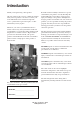
Introduction Thank you for purchasing a Toro product. All of us at Toro want you to be completely satisfied with your new product, so feel free to contact your local Authorized Service Dealer for help with service, genuine Toro replacement parts, or other information you may require. Whenever you contact your Authorized Service Dealer or the factory, always know the model and serial numbers of your product.
Contents Introduction 2 Contents 3 Safety Safe Operating Practices Safety and Instruction Decals 4 4 5 Specifications 6 Set-Up Instructions Adjusting The Front Shield Adusting The Rear Shield Adjusting The Turf Compensation Spring 7 7 7 7 Setting Height of Cut 9 Adjusting (Parallel) The Bedknife To The Reel 9 Setting Cutting Unit Attitude 10 Setting Attitude for New Cutting units: 11 Checking or Adjusting Attitude for Used Cutting Units 13 Leveling the Front Roller 14 Finalizing Height of Cut 14 M
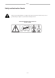
Safety Safe Operating Practices • Read, understand, and follow all instructions in the traction unit operator’s manual before operating the cutting unit. • Read, understand, and follow all instructions in this operator’s manual before operating the cutting unit. • Never allow children to operate the cutting units. Do not allow adults to operate traction unit or cutting units without proper instruction. Only trained operators who have read this manual should operate the cutting units.
Safety Safety and Instruction Decals Safety decals and instructions are visible to the operator and are located near my area of potential danger. Replace any decal that is damaged or lost. ON FRONT SHIELD OF THE CUTTING UNIT (Part No.
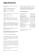
Specifications Reel Construction: Fairway reels. All welded. 5, 7 or 11 blades. Recommended Height-Of-Cut Range: 5 Blade—1” to 1-3/4” (25–44 mm) 7 Blade—1/2” to 1” (13–25 mm) 11 Blade—3/8” to 3/4” (10–19 mm) Note: Use bedknife Part No. 93-9774 for heights of cuts below 1/2” (13 mm). Reel Diameter: 7 in. (178 mm) Power Attachment: Reel motors feature quick disconnect for removal or installation onto the cutting unit. Cutting units can be driven from either end.
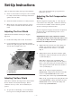
Set-Up Instructions plate, rotate the shield to the open position and tighten the capscrew. After you unbox the cutting unit, inspect the following: 1. Check each end of the reel for grease. Grease should be visibly evident in the reel bearings and internal splines of the reel shaft. 2. Insure that all nuts and bolts are securely fastened. 3. Make sure the carrier frame suspension operates freely and does not bind when moved back and forth.
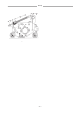
Set-Up Figure 2 –8–
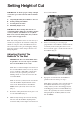
Setting Height of Cut the reel and bedknife. IMPORTANT. To insure proper setting of height of cut, these procedures must be followed in this order: A. B. C. D. 1 Adjusting (Parallel) the bedknife to the reel Setting cutting unit attitude Leveling the front roller Finalizing height of cut IMPORTANT: Each cutting unit must be set consistently.
Adjusting Height of Cut both ends of the reel to insure the bedknife did not move when tightening the pivot hub lock nuts. 2 Setting Cutting Unit Attitude 1 IMPORTANT: Cutting unit “attitude” has a significant impact on the performance of the cutting unit. Attitude refers to the angle of the knife relative to the ground (Fig. 6). Adjustable front and rear brackets allow for variable adjustment of the cutting unit attitude within the height-of-cut range.
Adjusting Height of Cut cutting unit to drag in the turf causing tufting. Therefore, minimum recommended attitude is 1 degree. For setting consistent cutting unit attitude, Toro strongly recommends using a two-screw gauge bar, Toro part no. 98-1852 (Fig. 7). The first screw is set for height of cut, and the second screw is set for cutting unit attitude. The second screw setting is an easy method of transferring cutting unit attitude to all cutting units on a machine. 4.
Adjusting Height of Cut Desired Height of Cut (mm) 10mm 13mm 16mm 19mm 22mm 25mm 29mm 32mm 35mm 38mm 41mm 45mm Desired Attitude (degrees) 2°* 4°* 6°* 8°* 2°* 4°* 6°* 8°* 2° 4° 6° 8° 2° 4° 6° 8° 2° 4° 6° 8° 2° 4° 6° 8° 2° 4° 6° 8° 2° 4° 6° 8° 2° 4° 6° 8° 2° 4° 6° 8° 2° 4° 6° 8° 2° 4° 6° 8° 2° 4° 6° 8° Second Screw “A” (mm) Fig. 7 4.6 5.9 – – 7.6 9.0 10.5 – 5.8 7.2 8.7 – 9.0 10.4 11.9 – 12.1 13.6 15.0 16.5 15.3 16.8 18.2 19.7 18.5 19.9 21.4 22.9 21.7 23.1 24.6 26.0 24.8 26.3 27.7 29.2 28.0 29.
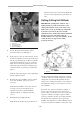
Adjusting Height of Cut touches the front roller. Verify front roller attitude at each end of the bedknife. Note: At this time there should be a small gap between the rear roller and gauge bar. 1 Checking or Adjusting Attitude for Used Cutting Units Note: As a starting point for adjusting cutting unit attitude, the cutting unit may be set up using the dimensions from Table 1. However, because of wear on the bedknife and reel, the following procedure must be used to ensure the correct attitude setting. 1.
Adjusting Height of Cut 7. Adjust the front roller to your desired cutting unit attitude: flat surface (Fig. 12). If needed, adjust the front height-of-cut rods until both ends of the roller are incontact with the level surface. Bedknife Angle (step 2) – Gauge Bar Angle (step 6) = Cutting Unit Attitude (degrees) Note: Moving the front roller down will decrease cutting unit attitude, while moving the front roller up will increase cutting unit attitude (Fig. 10).
Adjusting Height of Cut 1 2 3 Figure 13 1. First screw 2. Second screw 3.
Maintenance Backlapping Reelmaster 5500 Traction Units Note: Backlapping speed may be increased by moving the height-of-cut selection knob toward “13”. Each position will increase speed approximately 60 rpm. After changing selector, wait 30 seconds for the system to respond to the new speed target. DANGER POTENTIAL HAZARD Reels may stall while backlapping. WHAT CAN HAPPEN Reels may restart. Contact with rotating reels will cause serious injury.
Maintenance 13. When backlap operation has been completed, return the backlap knobs to the forward flow position, lower the seat and wash all lapping compound off the cutting units. Make the reelto-bedknife adjustment as often as needed. brush (Toro Part No. 29-9100). Never use a short handled brush (Fig. 15). 1 Figure 15 1. Long-handle brush 9. 9. If reels stall or become erratic while backlapping, the reel control light will begin to blink and the reels will turn off.
Maintenance Backlapping Reelmaster 6000 Traction Units 1 DANGER POTENTIAL HAZARD Reels may stall while backlapping. WHAT CAN HAPPEN Reels may restart. Contact with rotating reels will cause serious injury. Figure 17 1. Height-of-cut selection knob HOW TO AVOID THE HAZARD • Do not attempt to restart reels by hand or touch reels while backlapping. • 4. Make initial reel-to-bedknife adjustments appropriate for backlapping on all cutting units that are to be backlapped. 5.
Maintenance 8. Apply lapping compound with the long-handle brush supplied with the machine (Toro Part No. 29-9100). Never use a short-handle brush. 1 Figure 18 1. Long-handle brush 9. Figure 19 If the reels stall or become erratic while backlapping, the reel control light will begin to blink and the reels will turn off. If this occurs, turn the height-of-cut. selection knob one position closer to “A”. Then, toggle the Enable/Disable switch to the Disable position followed by the Enable position.
Maintenance -clockwise until no contact exists. Lubrication Each cutting unit has (7) grease fittings (Fig. 20) that must be lubricated regularly with No. 2 General Purpose Lithium Base Grease. The lubrication points are front roller (2), rear roller (2), reel bearing (2) and bedknife adjuster. 1 IMPORTANT. Lubricating cutting units immediately after washing helps purge water out of bearings and increases bearing life. 1. Wipe each grease fitting with a clean cloth. Figure 21 1.
Maintenance bearing adjusting nut to the bearing housing. 1 2 Figure 23 1. Set screw 2. Bearing adjusting nut Single-Point Spring Adjustment If the single-point adjustment assembly (Fig. 24) is removed for servicing, make sure the spring is compressed to a length of 1.25” (32 mm). This adjustment is attained by tightening the nut on knob shaft. Note: The single point adjustment assembly has left-handed threads. 32mm 1 2 Figure 24 1. Single-point adjust assembly 2.