
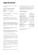
Operator's Manual


– 7 –
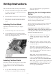
After you unbox the cutting unit, inspect the following:
1. Check each end of the reel for grease. Grease should
be visibly evident in the reel bearings and internal
splines of the reel shaft.
2. Insure that all nuts and bolts are securely fastened.
3. Make sure the carrier frame suspension operates
freely and does not bind when moved back and
forth.
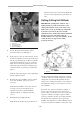
Adjusting The Front Shield
Adjust the front shield for desired grass clipping
dispersion.
1. Position the cutting unit on a flat, level surface.
2. Loosen the flange head capscrew that securs the
shield to the right side plate. Move the shield to the
desired angle and tighten the screw.
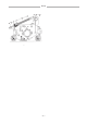
Figure 1
1. Front grass shield
2. Front capscrew
3. Rear grass shield
4. Rear capscrew
Adusting The Rear Shield
Under most conditions, best dispersion is attained when
the rear shield is closed (front discharge). When
conditions are heavy or wet, the rear shield may be
opened.
1. To open the rear shield (Fig. 1), loosen the flange
head capscrew securing the shield to the left side
plate, rotate the shield to the open position and
tighten the capscrew.
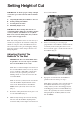
Adjusting The Turf Compensation
Spring
The turf compensation spring (Fig. 2), connecting the
carrier frame to the cutting unit, controls the amount of
fore-aft rotation available, and the amount of ground
clearance in transport and turn around.
The turf compensation spring also transfers weight from
the front to the rear roller. This helps reduce a wave
pattern in the turf.
IMPORTANT: Make spring adjustments with the
cutting unit mounted to the traction unit and lowered
to the shop floor. Refer to the traction unit operator’s
manual for mounting instructions.
1. Tighten the lock nut on the rear of the spring rod
until the gap (C) between the rear of the spring
bracket and front of the washer is 1” (26 mm)
(Fig. 2).
2. Tighten the hex nuts on the front end of the spring
rod until the compressed length (A) of the spring is
8” (203 mm) (Fig. 2).
Note: When cutting rough or undulating turf,
increase the compressed length (A) of the spring to
B=1/2” (216 mm) and the gap (C) between the rear
of the spring bracket and the front of the washer to
1-1/2” (39 mm) (Fig. 5).
Note: As the compressed spring length (A)
DECREASES, weight transfer from the front roller
to the rear roller INCREASES and the carrier
frame/cutting unit rotation angle (B) DECREASES.
Note: As the gap (C) between the spring bracket and
washer INCREASES, cutting unit ground clearance
DECREASES and the carrier frame/cutting unit
rotation angle (B) INCREASES.
Set-Up Instructions
4
2
3
1