Form No. 3326-329 Dethatcher Kit Reelmaster 5500-D/6000-D Series Attachment Model No. 03872—Serial No.
Contents Contents . . . . . . . . . . . . . . . . . . . . . . . . . . . . . . . . . . . Introduction . . . . . . . . . . . . . . . . . . . . . . . . . . . . . . . . Safety . . . . . . . . . . . . . . . . . . . . . . . . . . . . . . . . . . . . . Safe Operating Practices . . . . . . . . . . . . . . . . . . . . Safety and Instruction Decals . . . . . . . . . . . . . . . . Specifications . . . . . . . . . . . . . . . . . . . . . . . . . . . . . . . Set–Up . . . . . . . . . . . . . . . . . . . . . . . . . . . .
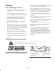
• Remove all debris or other objects that might be picked up and thrown by the dethatching unit reel blades. Keep all bystanders away from the working area. Safety Safe Operating Practices • If the dethatching blades strike a solid object or the unit vibrates abnormally, stop and shut the engine off. Check dethatching unit for damaged parts. Repair any damage before restarting and operating the dethatching unit.
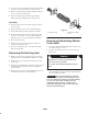
Specifications Reel construction Blades and spacers bolted to square shaft Dethatching range Up to 1/4 in. deep blade penetration Reel diameter Power Reel bearings Roller adjustment 7–1/4 in. Hydraulic motor splined to reel shaft Self aligning, roller ball type with cast housing and eccentric collar lock with setscrew Front-fixed, adjustable rear roller Set–Up Note: Determine the left and right sides of the machine from the normal operating position.
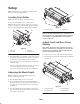
Setup Note: Determine the left and right sides of the machine from the normal operating position. 2 Leveling Front Roller Note: Front roller has been leveled at the factory. 1. Place the dethatching reel on a level surface. 1 Note: To raise rear roller off the ground, place a flat bar under the dethatching reel blades (Fig. 1). Be sure that the bar covers the full length of the dethatching reel blades. Figure 2 1. Gauge bar (1/4”) 4 2.
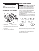
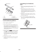
Mount Dethatching Reel Caution Important When lowering dethatching reels, care must be taken to prevent damage to the reel blades due to contact with a concrete floor or a paved surface. Do not open rear shield so it is higher than level to ground The dethatcher units can be installed at any of the five or seven mounting locations on the traction unit. Figure 5 shows the orientation of the hydraulic drive motor for each of the locations.
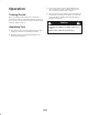
Operation 3. Power requirements to operate the dethatching reels will vary with turf and soil conditions. Travel speed may need to be reduced in some conditions. Training Period 4. When operating in turf conditions where much debris is encountered, or unusually heavy thatch, open the front and rear discharge shields to help allow the debris to discharge from the reel. Before operating the dethatching reels, evaluate the performance of the reel at the desired setting.
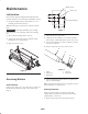
.188 in. dia. (2) Maintenance .625 in. dia. Lubrication .625 in. Each unit has (3) grease fittings that must be lubricated regularly with No. 2 General Purpose Lithium Base Grease. .625 in. 1/4–20 UNC (2) 1. The grease fitting locations and quantities are: reel bearings (2) and carrier frame (1). Note: Reel bearings are located on reel side of each side plate. 1.05 in. 1.05 in. Important Lubricating immediately after washing helps purge water out of bearings and increases bearing life.
2. Loosely secure roller assembly in bench vise and lightly tap one end of roller shaft until free from housing. 3. Remove second bearing from shaft. Support bearing on inner race and tap on roller shaft. 4. Inspect bearings, shaft, and snap ring for damage. Replace damaged components. Re-assemble roller. 1 Assembly 1. Press bearing onto one end of shaft. Apply pressure to inner race only. 2 2. Install snap ring on same end as assembled bearing. Figure 9 3.
Assembling the Dethatcher Reel This end in vise 1 1. Slide the reel bearing locking collars onto the reel shaft with the locking collars facing inward and not tightened. 2. Place the dethatcher shaft assembly into the frame assembly. Through the side plates, slide a bearing housing onto the dethatcher shaft. Secure the bearing housing to the side plate with the capscrews previously removed. Tighten the capscrews to 14–18 ft.-lb. (19–24 N⋅m). 6 5 4 3 3.
The Toro General Commercial Products Warranty A Two-Year Limited Warranty Conditions and Products Covered The Toro Company and its affiliate, Toro Warranty Company, pursuant to an agreement between them, jointly warrant your 1996 or newer Toro Commercial Product (“Product”) purchased after January 1, 1997, to be free from defects in materials or workmanship for two years or 1500 operational hours*, whichever occurs first.