Form No. 3392-160 Rev A Verticutter Reelmaster® 6000-D Series Cutting Unit Model No. 03877—Serial No. 316000001 and Up Register at www.Toro.com.
This manual identifies potential hazards and has safety messages identified by the safety-alert symbol (Figure 1), which signals a hazard that may cause serious injury or death if you do not follow the recommended precautions. WARNING CALIFORNIA Proposition 65 Warning This product contains a chemical or chemicals known to the State of California to cause cancer, birth defects, or reproductive harm. Figure 1 1. Safety-alert symbol This product complies with all relevant European directives.
Safety is advisable and required by some local ordinances and insurance regulations. • Tie back long hair. Do not wear jewelry. This machine has been designed in accordance with EN ISO 5395:2013. • Remove all debris or other objects that might be picked up and thrown by the reel blades of the cutting unit. Keep all bystanders away from the working area. Improper use or maintenance of this equipment can result in injury or death.
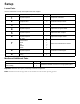
Setup Loose Parts Use the chart below to verify that all parts have been shipped. Procedure Description 1 2 3 4 5 6 7 8 9 Use Qty. No parts required – Inspect the verticutter. Transport roller 2 Install the transport rollers. No parts required – Adjust the blade depth. No parts required – Adjust the rear grass shield. No parts required – Adjust the roller scrapers. No parts required – Adjust the transport rollers.
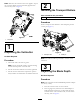
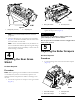
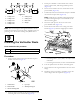
Note: Whenever the verticutter has to be tipped to expose the verticutter blades, use the kickstand (supplied with traction unit); refer to Figure 2. 2 Installing the Transport Rollers Parts needed for this procedure: 2 Transport roller Procedure Secure a transport-roller bracket to each side-plate pin with a cotter pin (Figure 3). Figure 2 1. Kickstand 1 Inspecting the Verticutter Figure 3 1. Transport roller 2.
Figure 5 1. Rear grass shield 2. Pivot cap screw Figure 4 1. Gauge bar (1/4 inch) 2. Rotate the grass shield to the desired setting, and tighten the cap screws (Figure 5). 2. Adjusting bolt WARNING Note: The verticutter blades must not touch the gauge bars. Opening the rear shield too much could cause personal injury due to thrown debris. 3. Turn the adjusting bolt on each height-of-cut bracket (Figure 4) so that the reel blades come in contact with the level surface on both ends.
2. Move the scraper rods in or out to attain 0.0 to 0.75 mm (0.0 to 0.03 inch) clearance between the scraper and the roller. 7 3. Ensure that the scraper rod is parallel to the roller and to the level surface. Mounting the Lift Brackets and Chains 4. Tighten the flange nuts to lock the adjustment.
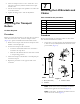
Note: Rotate the brackets 10° to the outboard side of the machine. 2. On lift arms 2 and 3, position the brackets and U-bolts 38 cm (15 inches) behind the center line of the pivot knuckle (Figure 8). 4. Tighten all the U-bolt nuts to 52 to 65 N∙m (38 to 48 ft-lb). 5. Mount a lift chain to each chain bracket with a screw, a washer, and a nut, positioning them as shown in Figure 10. Figure 10 1. Lift chain Figure 8 1. 38 cm (15 inches) 2. Chain bracket 8 2. Lift arm 3 Installing the Counterweights 3.
3. Secure pivot knuckle to carrier frame with a thrust washer, a flat washer, and a flange-head cap screw (Figure 12). 4. Insert a thrust washer onto the vertical shaft of the pivot knuckle (Figure 12). 5. If removed, insert the vertical shaft of the pivot knuckle into the lift-arm pivot hub (Figure 12). Figure 11 1. Cutting unit 1 6. Cutting unit 6 2. Cutting unit 2 7. Cutting unit 7 3. Cutting unit 3 8. Reel motor 4. Cutting unit 4 9.
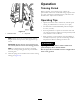
Operation Training Period Before operating the verticutter reels, evaluate the performance of the reel at the desired setting. Operate them in a clear, unused area to determine if they will achieve the desired results. Adjust them as desired. Operating Tips • Operate the traction unit at full throttle, full reel speed (setting 11) and between 5 to 8 km/h (3 to 5 mph). • The maximum recommended blade penetration depth is 6 mm (1/4 inch).
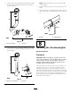
Maintenance Adjusting the Reel Bearings To ensure long life of the reel bearings, periodically check for any reel end play. Check and adjust the bearings as follows: Lubricating the Verticutter 1. Hold on to the reel shaft and try to move the reel assembly side to side (Figure 16). Each cutting unit has 7 grease fittings that you must lubricate weekly with No. 2 lithium grease. The lubrication points are the front roller (2), the rear roller (2), the reel bearings (2), and the bed-knife adjuster.
Replacing the Blades 5. Continue to install spacers and blades in this manner until the full complement of blades have been installed. Removing the Blades from the Shaft Note: When properly assembled, the blades are staggered in such a manner as to appear like a helix. 1. Secure the end of the verticutter shaft that has only 1 washer and 1 nut in a vise. 6. Install the small spacer to the shaft. 7. Apply blue Loctite 242 to the nut. 2.
Notes: 13
Declaration of Incorporation The Toro Company, 8111 Lyndale Ave. South, Bloomington, MN, USA declares that the following unit(s) conform(s) to the directives listed, when installed in accordance with the accompanying instructions onto certain Toro models as indicated on the relevant Declarations of Conformity. Model No. Serial No.
International Distributor List Distributor: Agrolanc Kft Asian American Industrial (AAI) B-Ray Corporation Brisa Goods LLC Casco Sales Company Ceres S.A. CSSC Turf Equipment (pvt) Ltd. Cyril Johnston & Co. Cyril Johnston & Co. Fat Dragon Femco S.A. FIVEMANS New-Tech Co., Ltd ForGarder OU G.Y.K. Company Ltd. Geomechaniki of Athens Golf international Turizm Hako Ground and Garden Hako Ground and Garden Hayter Limited (U.K.) Hydroturf Int. Co Dubai Hydroturf Egypt LLC Irrimac Irrigation Products Int'l Pvt Ltd.
The Toro Warranty A Two-Year Limited Warranty Conditions and Products Covered The Toro Company and its affiliate, Toro Warranty Company, pursuant to an agreement between them, jointly warrant your Toro Commercial product (“Product”) to be free from defects in materials or workmanship for two years or 1500 operational hours*, whichever occurs first. This warranty is applicable to all products with the exception of Aerators (refer to separate warranty statements for these products).