
Operator's Manual

2.Movethescraperrodsinorouttoattain0.0to0.75
mm(0.0to0.03inch)clearancebetweenthescraper
andtheroller.
3.Ensurethatthescraperrodisparalleltotherollerand
tothelevelsurface.
4.Tightentheangenutstolocktheadjustment.
6
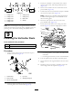
AdjustingtheTransport
Rollers
NoPartsRequired
Procedure
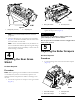
Beforeyoulowertheverticutterstotheshopoororremove
themfromthetractionunit,lowerthetransportrollers
(Figure6)toprotectthebladesfromhardsurfacecontact.
1.Removethecotterpinthatsecuresthetransportroller
brackettotheside-platepin.
2.Positionthetransportrollerasfollows:
•Lowertherollerbracketbeforetheverticutteris
loweredtotheshopoor.
•Raisetherollerbracketaftertheverticutterisraised
totheoperatingposition.
3.Securethetransportrollerbrackettotheside-platepin
withthecotterpin.
4.Repeattheprocedureontheoppositeendofthe
verticutter.
7
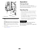
MountingtheLiftBracketsand
Chains
Partsneededforthisprocedure:
1
Liftchain
1
Chainbracket
1U-bolt
3Nut
1Washer
1
Screw
Procedure
MountachainbrackettoeachliftarmwithaU-boltand2
nuts.Positionthebracketsasfollows:
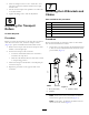
1.Onliftarms1,4,and5,positionthechainbracketsand
U-bolts38cm(15inches)behindthecenterlineofthe
pivotknuckle(Figure7).
Figure7
1.38cm(15inches)3.Liftarms1and5
2.Liftarm4
Note:Onliftarms1and5,thebracketsshouldbe
rotatedtotheright10°fromvertical(Figure7).
Note:Onliftarm4,thebracketshouldberotatedto
theleft10°fromvertical(Figure7).
7