
Operator's Manual
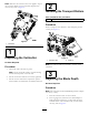
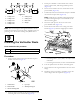

2.Onliftarms2and3,positionthebracketsandU-bolts
38cm(15inches)behindthecenterlineofthepivot
knuckle(Figure8).
Figure8
1.38cm(15inches)2.Liftarm3
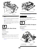
3.Onliftarms6and7,positionthebracketsandU-bolts
36.8cm(14-1/2inches)behindthecenterlineofthe
pivotknuckle(
Figure9
1.36.8cm(14-1/2inches)2.Liftarm7
Note:Rotatethebrackets10°totheoutboardside
ofthemachine.
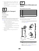
4.TightenalltheU-boltnutsto52to65N∙m(38to48
ft-lb).
5.Mountaliftchaintoeachchainbracketwithascrew,a
washer,andanut,positioningthemasshowninFigure
10.
Figure10
1.Liftchain2.Chainbracket
8
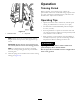
InstallingtheCounterweights
NoPartsRequired
Procedure
Important:Whenloweringtheverticutterreels,take
caretopreventdamagetothereelbladesduetocontact
withaconcreteoororapavedsurface.Lowerthe
transportrollersbeforeloweringtheverticutterstoa
concreteoororapavedsurface.
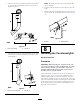
Youcaninstalltheverticuttersatanyofthe7locationson
thetractionunit.Figure11showstheorientationofthe
hydraulicdrivemotorforeachofthelocations.Foranyof
thelocationsrequiringthemotortobemountedontheright
endoftheverticutters,installacounterweightontheleftend
oftheverticutters.Forthelocationsrequiringthemotorto
bemountedontheleftend,installacounterweightonthe
rightendoftheverticutters.
8