
Operator's Manual
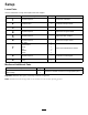
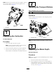
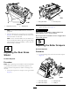
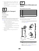
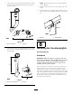
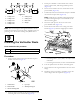
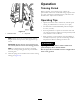

Figure11
1.Cuttingunit16.Cuttingunit6
2.Cuttingunit27.Cuttingunit7
3.Cuttingunit3
8.Reelmotor
4.Cuttingunit4
9.Weight
5.Cuttingunit5
Note:Thecounterweightsareshippedinstalledtotheleft
endoftheverticutters.The2capscrews,shippedintheloose
partsbag,aretobeusedforsecuringthehydraulicmotor.
9
InstallingtheVerticutterReels
Partsneededforthisprocedure:
1
Screw
1
O-ring
Procedure
1.Insertathrustwasherontohorizontalshaftofpivot
knuckleasshowninFigure12.
Figure12
1.Carrierframe
4.Lynchpin
2.Pivotknuckle
5.Steeringlockingpin
3.Lift-armsteeringplate
2.Insertthehorizontalshaftofthepivotknuckleintothe
mountingtubeofthecarrierframe(Figure12).
3.Securepivotknuckletocarrierframewithathrust
washer,aatwasher,andaange-headcapscrew
(Figure12).
4.Insertathrustwasherontotheverticalshaftofthe
pivotknuckle(Figure12).
5.Ifremoved,inserttheverticalshaftofthepivotknuckle
intothelift-armpivothub(Figure12).
Note:Guidethepivotknuckleinplacebetweenthe
2rubbercenteringbumpersintheundersideofthe
lift-armsteeringplate.
6.Insertthelynchpinintothecrossholeonthe
pivot-knuckleshaft(Figure12).
7.Securethelift-armchaintothecuttingunitchain
bracket(Figure13)withthesnapperpinasfollows:
Figure13
•Oncuttingunits1,4,5,6,and7,useonly6ofthe
chainlinks.
•Oncuttingunits2and3,useall7ofthechainlinks.
8.Coatthesplinesofthereelmotorwithcleangrease.
9.OilthereelmotorO-ringandinstallitontothemotor
ange.
10.Installthemotorbyrotatingitclockwisesothatthe
motorangesclearthecapscrews(Figure14).
9