Form No. 3375-837 Rev C 18 and 22 inch DPA Cutting Unit Reelmaster® 3550 Series Traction Unit Model No. 03911—Serial No. 313000001 and Up Model No. 03912—Serial No. 313000001 and Up Model No. 03913—Serial No. 313000001 and Up Register at www.Toro.com.
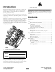
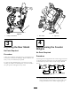
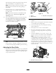
Figure 2 Introduction 1. Safety alert symbol Read this information carefully to learn how to operate and maintain your product properly and to avoid injury and product damage. You are responsible for operating the product properly and safely. This manual uses 2 other words to highlight information. Important calls attention to special mechanical information and Note emphasizes general information worthy of special attention. You may contact Toro directly at www.Toro.
Safety could get caught in moving parts. Always wear long pants and substantial shoes. Wearing safety glasses, safety shoes and a helmet is advisable and required by some local ordinances and insurance regulations. Hazard control and accident prevention are dependent upon the awareness, concern, and proper training of the personnel involved in the operation, transport, maintenance, and storage of the machine. Improper use or maintenance of the machine can result in injury or death.
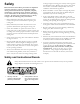
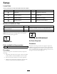
Setup Loose Parts Use the chart below to verify that all parts have been shipped. Procedure Description 1 2 3 4 Use Qty. Cutting unit 1 Inspect the cutting unit No parts required – Use the kickstand when tipping the cutting unit No parts required – Adjust the rear shield No parts required – Mount the counter weights Media and Additional Parts Description Use Qty.
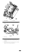
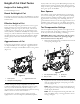
g020159 g020158 Figure 4 Figure 3 1. Rear shield 1. Cutting unit kickstand 2. Cap screw 4 3 Repositioning the Counter Weights Adjusting the Rear Shield No Parts Required No Parts Required Procedure Procedure Under most conditions, best dispersion is attained when the rear shield is closed (front discharge). When conditions are heavy or wet, rear shield may be opened. All cutting units are shipped with the counter weight mounted to the left end of the cutting unit.
2 2 g020160 Figure 6 1. Counter weight 2. Lock nuts 2. Remove the 2 lock nuts from the right side plate (Figure 7). g026187 Figure 7 1. Lock nut (2) 3. Install the counter weight to the right end of the cutting unit and secure with the 2 lock nuts previously removed. 4. Install the 2 reel motor mounting lock nuts to the left side plate of the cutting unit (Figure 7).
Product Overview Specifications. Model Number Net Weight 03911 39 kg (86 lb.) 03912 40 kg (88 lb.) 03913 43 kg (94 lb.) Cutting Unit Accessories and Kits (see parts catalog for part numbers) Full Front Roller: Helps produce more pronounced striping (repeated cutting in the same direction/path), however, effective height of cut is raised and quality of cut is reduced.
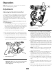
Operation Note: Determine the left and right sides of the machine from the normal operating position. Adjustments Adjusting the Bedknife to the Reel Use this procedure to set the bedknife to the reel and to check the condition of the reel and bedknife and their interaction. After completing this procedure, always test the cutting unit performance under your field conditions. You may need to make further adjustments to obtain optimal cutting performance.
sides prevents the shim from passing through on both sides. The bedknife is now parallel to the reel. Note: This procedure should not be needed on daily adjustments, but should be done after grinding or disassembly. 9. From this position (i.e. one click in and shim not passing through) turn the bedbar adjusters clockwise two clicks each. g020161 Note: Each click turned moves the bedknife 0.018 mm (0.0007 inches). Do not over tighten the adjusting screws. Figure 11 1. Spacer 3.
Height of Cut Chart Terms Zoysia) while cool season grasses (Bent, Bluegrass, Rye) may require normal to more aggressive setups. More aggressive setups cut more grass off by allowing the spinning reel to pull more grass up into the bedknife. Height of Cut Setting (HOC) The desired Height of Cut. Rear Spacers Bench Set Height of Cut The number of rear spacers determines the aggressiveness of cut for the cutting unit.
Chain Links The location at which the lift arm chain is attached determines the rear roller pitch angle (Figure 15). Figure 15 1. Lift chain 2. U-Bracket 3.
Groomer These are the recommended height of cut settings when a groomer kit is installed on the cutting unit. Height of Cut Chart HOC Setting Aggressiveness of Cut No. of Rear Spacers No. of Chain Links With Groomer kits installed 0.64 cm (0.250 inches) Less Normal More 0 0 1 4 4 3 Y Y - 0.95 cm (0.375 inches ) Less Normal More 0 1 2 4 3+ 3+ Y Y - 1.27 cm (0.500 inches) Less Normal More 0 1 2 4 4 3+ Y Y Y 1.56 cm (0.625 inches) Less Normal More 1 2 3 4 4 3+ Y Y - 1.91 cm (0.
Adjusting the Height of Cut Note: For heights of cut greater than 2.54 cm (1.000 inch) the High Height of Cut Kit must be installed. 1. Loosen locknuts securing height-of-cut brackets to cutting unit side plates (Figure 16). Figure 18 Important: When set properly, the rear and front rollers will contact the gauge bar and the screw will be snug against the bedknife. This ensures that the height-of-cut is identical at both ends of the bedknife. g020166 Figure 16 1. Adjusting screw 3.
Bedknife/ Height of Cut Chart Premium Low HOC Bedknife Reel Size Part No. 18 inch, 11 blade (Production) 18 inch, 8 blade (Optional) 125–2770 22 inch, 8 blade (Optional) 125–2771 Bedknife Lip Height Height of Cut 5.6 mm (.220 inch) 6.4–12.7 mm (.250-.500 inch) Low HOC Bedknife Reel Size Part No. Bedknife Lip Height Height of Cut 18 inch, 8 & 11 blade (Optional) 121-3167 5.6 mm (.220 inch) .6.4–12.7 mm (.250-.
Figure 20 Note: If excessive contact/reel drag is evident it will be either necessary to backlap, reface the front of the bedknife, or regrind the cutting unit to achieve the sharp edges needed for precision cutting (Refer to the Toro Manual for Sharpening Reel and Rotary Mowers, Form No. 09168SL). Important: Light contact is preferred at all times. If you do not maintain light contact, the bedknife and reel edges will not sufficiently self-sharpen and will dull after a period of operation.
Servicing the Bedknife The bedknife service limits are listed in the following charts. Important: Operating the cutting unit with the bedknife below the “service limit” may result in poor after-cut appearance and reduce the structural integrity of the bedknife for impacts. Bedknife Service Limit Chart Premium Low HOC Bedknife Reel Size Part No.
Recommended Top and Front Bedknife Grind Angles (Figure 22). 2 3 g025579 Figure 22 1. Bedknife service limit * 2. Top grind angle 3.
Maintenance Lubrication Each cutting unit has (4) grease fittings that must be lubricated regularly with No. 2 General Purpose Lithium Base Grease. The lubrication points are the front roller (2) and the rear roller (2). Also, after every 250 hours or whenever the reel motor is removed from the cutting unit, apply grease to the spline insert (Figure 24). Figure 25 Note: Lubricating cutting units immediately after washing helps purge water out of bearings and increases bearing life. 1.
washer outside each of the nylon washers (Figure 27). Torque bedbar bolts to 27-33 (37-45 N-m). Tighten the locknuts equally, on each side, until the outer steel washers cannot be rotated by hand. Then, loosen the lock nuts until the outer steel washers just rotate by hand, yet the bedbar end play is removed. Note: Overtightening the lock nuts can deflect the side plates and bedbar which can affect the reel/bedknife contact. Note: The washers on the inside may have a gap. 3.
Servicing the HD Dual Point Adjusters (DPA) 7. Loosely install the hardened washer, spring and spring tension nut onto adjuster screw. 8. Install the bedbar, positioning the mounting ears between washer and bedbar adjuster. 1. Remove all parts (refer to Installation Instructions for HD DPA Kit Model No. 120–7230 and to Figure 29). 9. Secure the bedbar to each side plate with the bedbar bolts (nuts on bolts) and 6 washers. A nylon washer is to be positioned on each side of side plate boss.
Servicing the Roller Rebuild Kit includes all the bearings, bearing nuts, inner seals and outer seals to rebuild a roller. The Roller Rebuild Tool Kit includes all the tools and the installation instructions required to rebuild a roller. Refer to your parts catalog or contact your distributor for assistance. A Roller Rebuild Kit, Part No. 114–5430 and a Roller Rebuild Tool Kit, Part No. 115–0803 (Figure 30) are available for servicing the roller. The Roller Figure 30 1. Rebuild kit (Part No.
Notes: 22
Declaration of Incorporation The Toro Company, 8111 Lyndale Ave. South, Bloomington, MN, USA declares that the following unit(s) conform(s) to the directives listed, when installed in accordance with the accompanying instructions onto certain Toro models as indicated on the relevant Declarations of Conformity. Model No. 03911 Serial No.
The Toro Total Coverage Guarantee A Limited Warranty Conditions and Products Covered The Toro Company and its affiliate, Toro Warranty Company, pursuant to an agreement between them, jointly warrant your Toro Commercial product (“Product”) to be free from defects in materials or workmanship for two years or 1500 operational hours*, whichever occurs first. This warranty is applicable to all products with the exception of Aerators (refer to separate warranty statements for these products).