Form No. 3375-892 Rev D Rear Roller Brush Kit Reelmaster® 3550 Series 18-inch and 22-inch Cutting Units Model No. 03918 Operator's Manual This product complies with all relevant European directives. For details please see the separate product specific Declaration of Conformity (DOC) sheet. The rear roller brush kits are mounted to the reel mowers on a ride-on machine and is intended to be used by professional, hired operators in commercial applications.
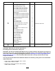
Procedure Description Qty.
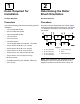
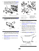
1 2 Items Required for Installation Determining the Roller Brush Orientation No Parts Required No Parts Required Procedure Procedure Acquire the following tools before proceeding with the installation: All cutting units are shipped with the counter weight mounted to the left end of the cutting unit. Use Figure 1 to determine the position of the roller brush and reel motors.
Procedure 3 Installing the Roller Brush Parts needed for this procedure: 3 18-inch Roller brush housing 2 22-inch Roller brush housing 10 Hex-socket bolt (3/8 x 1 inch) 1 18-inch Right roller brush assembly 1 22-inch Right roller brush assembly 2 18-inch Left roller brush assembly 1 22-inch Left roller brush assembly 5 Shoulder bolt 1 18-inch Right belt cover/plate assembly 1 22-inch Right belt cover/plate assembly 2 18-inch Left belt cover/plate assembly 1 22-inch Left belt cover/pl
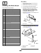
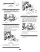
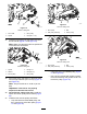
7. For 22 inch cutting units (#2 and #3 (Figure 1) roller brush side only). Remove the sideplate by removing any hardware in the way and loosening the rear roller clamp nuts (Figure 4). g021425 g021341 Figure 6 Figure 4 1. Sideplate 8. 2. Rear roller clamp nut For 22 inch cutting units (#2 and #3 (Figure 1) roller brush side only). Remove bolts from sideplate. 1. 18-inch drive shaft 4. Threaded insert (Left insert has ring on it) 2. Apply 242 Loctite (blue) here 5.
g020394 Figure 8 22-inch cutting unit 1. O-ring 15. On the 18-inch cutting unit only, remove the straight grease fitting near the roller brush housing and install the 90° grease fitting in the same spot (Figure 9). g021427 Figure 11 22-inch cutting unit 1. Roller brush housing 17. 2. Cutting unit bolts removed Remove the 2 flange lock nuts securing each roller bracket to the side plates (Figure 12). Note: Do not remove the bolts.
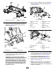
21. Apply a coating of grease to the inner diameter of the grommet in the bearing housing (Figure 15 and Figure 16). g021404 g021428 Figure 13 1. Left roller brush assembly 19. Figure 15 18-inch cutting unit 2. Roller brush mounting bracket Slide each excluder seal outward until the lip seals are in light contact with each bearing housing (Figure 14). 1. Roller-brush mounting bracket 5. Roller-brush pivot plate assembly 2. Roller-brush bearing housing 6. Grommet in bearing housing 3. Bolt 7.
Note: The roller brush pivot plate is properly seated when there is no resistance from the rubber grommet and it pivots freely. Note: Ensure that the idler-pulley assembly is installed on the bottom as shown in Figure 15 and Figure 16. 25. Apply 242 Loctite (blue) to the 2 bolts (5/16 x 5/8 inch) and use them to mount the brush plate to the roller brush bearing housing (Figure 15 and Figure 16). Torque the bolts to 20–25 N⋅m (15–19 ft-lb). 26.
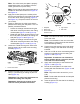
g020295 Figure 21 18-inch cutting unit g020294 Figure 19 18-inch cutting unit 1. Drive shaft 3. Drive pulley 2. Spacer 4. Bolt (3/8 x 1-1/4”) 34. 1. Drive pulley 3. Belt 2. Idler-pulley assembly 4. Driven pulley Insert the drive pulley into the spacer and onto the drive shaft (Figure 19 and Figure 20). Note: Make sure the pulley tabs are positioned in the slot in the drive shaft. g021350 Figure 22 22-inch cutting unit g021349 Figure 20 22-inch cutting unit 1. Spacer 4. Flange nut 2.
g021351 Figure 25 22-inch cutting unit 1. Ruler • The outer faces of the drive and driven pulleys should be in line within .76 mm (.030 inch). • If the pulleys are not aligned, align the pulleys; refer to Checking and Adjusting the Pulley Alignment (page 13). g020390 Figure 23 1. Belt • If the pulleys are aligned, continue with the 2. 9/16 inch deep-well socket installation. • Do not use the idler pulley to check Important: Make sure the ribs on the belt 38. 39. alignment.
4 Installing the 18-inch High Height-of-Cut Brush (Optional) g021352 Figure 27 22-inch cutting unit No Parts Required Procedure 1. Belt cover 41. Install the High Height of Cut Brush, Part No. 121-3199 when cutting above 2.5 cm (1 inch) height-of-cut (i.e., 5 or more spacers installed below the side plate pad). Lubricate the grease fittings on each of the roller brush bearing housings with No. 2 general-purpose, lithium-base grease (Figure 28). 1.
g020301 Figure 31 1. Non–drive bearing housing 3. Brush shaft g020302 2. Excluder seal 3. Remove the 2 J-bolts and nuts (Figure 32). 4. Slide the existing brush off the brush shaft (Figure 32). 5. Loosen the 2 bolts, washers, and nuts securing the drive bearing housing to the bearing housing mounting bracket (Figure 32). 6. Slide the high height of cut brush onto the brush shaft (Figure 32). 7. Clamp the brush onto the shaft with the 2 J-bolts and nuts previously removed (Figure 32).
Maintenance Note: Put a 1/2 inch wrench on the roller brush shaft flats to keep it from rotating. 1. Ensure that the brush is parallel to the roller with 1.50 mm (0.06 inch) clearance to light contact. 2. Grease fittings every 50 hours or after every washing. 3. When replacing roller brush, torque J-bolts to 2 to 3 N⋅m (20 to 25 in-lb). 4. When replacing the brush shaft driven pulley, torque the nut to 36 to 45 N⋅m (27 to 33 ft-lb). 5.
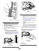
• Start the belt on the driven pulley (Figure • 21). Use a 9/16 inch deep-well socket to rotate the brush assembly and guide the belt onto the driven pulley (Figure 36). 2. Insert a long-handled pry bar (recommended 3/8" x 12" with screwdriver handle) through the back of the cutting reel, closest to the side of the cutting unit that you will be torquing (Figure 37). 3. Place the pry bar against the weld side of the reel support plate (Figure 37).
Restraining the Reel for Installing Threaded Inserts 1. Insert a long-handled pry bar (recommended 3/8" x 12" with screwdriver handle) through the front of the cutting reel, closest to the side of the cutting unit that you will be torquing (Figure 38). 2. Place the pry bar against the weld side of the internal cutting reel reinforcement (Figure 38). Note: The pry bar should contact a blade at the front, the reel shaft, and a blade at the back of the back of the reel, locking it in place.
Declaration of Incorporation The Toro Company, 8111 Lyndale Ave. South, Bloomington, MN, USA declares that the following unit(s) conform(s) to the directives listed, when installed in accordance with the accompanying instructions onto certain Toro models as indicated on the relevant Declarations of Conformity. Model No. 03918 Serial No.