
Operator's Manual


Maintenance
1.Ensurethatthebrushisparalleltotherollerwith
1.50mm(0.06inch)clearancetolightcontact.
2.Greasettingsevery50hoursorafterevery
washing.
3.Whenreplacingrollerbrush,torqueJ-boltsto2
to3N⋅m(20to25in-lb).
4.Whenreplacingthebrushshaftdrivenpulley,
torquethenutto36to45N⋅m(27to33ft-lb).
5.Whenreplacingthebrushdrivepulley,torque
theboltto47to54N⋅m(35to40ft-lb).
Important:Backlappingattheincorrectreel
speedmayloosenandstripthedrivepulley
threads.RefertotheCuttingUnitOperator’s
Manualforbacklappingprocedure.
6.Rollerbrush,idlerbearing,andbeltare
consideredconsumableitems.
CheckingandAdjustingthe
PulleyAlignment
1.Thedrivenpulley(atrollerbrushshaft)can
moveinorout(Figure33).
Note:Makenoteofwhichwaythepulleyneeds
tomove.
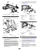
g020303
Figure33
1.Drivenpulley3.Drivenpulleynut
2.Idler-pulleyassembly
2.Whilerotatingthereel,whichwillrotatethedrive
pulley,prythebeltoffthedrivepulley(Figure33
Note:Wearapaddedgloveoruseaheavyrag
torotatethereel.
3.Removethelocknutsecuringthedrivenpulley
tothebrushshaft(Figure33orFigure34).
Note:Puta1/2inchwrenchontherollerbrush
shaftatstokeepitfromrotating.
4.Removethedrivenpulleyfromtheshaft(Figure
34).
Note:Ifthepulleyneedstomoveout,addone
0.8mm(0.032inch)thickspacer(Figure34).If
thepulleyneedstomovein,removetheexisting
0.8mm(0.032inch)thickspacer.
5.Installthepulley.
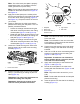
g009077
Figure34
1.Locknut
3.Spacer(0.8mm(0.032
inch)thick)
2.Drivenpulley
4.Brushshaftats
6.Whileholdingtherollerbrushshaftats,secure
thepulleyontheshaftwiththe3/8–16ange
nutpreviouslyremoved.
Note:Seatthelocknutthentorqueitto36to
45N⋅m(27to33ft-lb).
7.Installthebeltontothepulleysasfollows:
•Loopthebeltaroundthedrivepulleyand
thenoverthetopoftheidlerpulley(Figure
21).
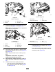
g009059
Figure35
1.Drivepulley3.Drivenpulley
2.Idler-pulleyassembly4.Belt
13