
Operator's Manual


•Startthebeltonthedrivenpulley(Figure
21).
•Usea9/16inchdeep-wellsockettorotate
thebrushassemblyandguidethebeltonto
thedrivenpulley(Figure36).
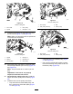
g020390
Figure36
1.Belt
2.9/16inchdeep-wellsocket
Important:Makesuretheribsonthebelt
areproperlyseatedinthegroovesineach
pulley.Also,makesurethebeltisinthe
centeroftheidlerpulley.
8.Checkthepulleyalignmentagain;repeatthis
procedureifnecessary.
RestrainingtheReel
WARNING
Thecuttingreelbladesaresharpandcapable
ofamputatinghandsandfeet.
•Keepyourhandsandfeetoutsideofthe
reel.
•Ensurethatthereelisrestrainedbefore
servicingit.
RestrainingtheReelforRemoving
ThreadedInserts
1.Loosentheshield-boltontheleftsideofthe
cuttingunitandraisetherearshield(Figure37).
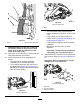
2.Insertalong-handledprybar(recommended
3/8"x12"withscrewdriverhandle)throughthe
backofthecuttingreel,closesttothesideofthe
cuttingunitthatyouwillbetorquing(Figure37).
3.Placetheprybaragainsttheweldsideofthe
reelsupportplate(Figure37).
Note:Inserttheprybarbetweenthetopofthe
reelshaftandthebacksof2reelbladessothat
thereelwillnotmove.
Important:Donotcontactthecuttingedge
ofanybladeswiththeprybar;thismay
damagethecuttingedgeand/orcauseahigh
blade.
Important:Theinsertontheleftsideof
thecuttingunithasleft-handthreads.The
insertontherightsideofthecuttingunithas
right-handthreads.
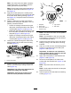
g280383
Figure37
1.Threadedinsertfor
removal
4.Reelshaft
2.Loosentheshieldbolt.5.Reelsupportplate
3.Rearshield6.Prybarinsertedalong
theweldsideofthereel
supportplate.
4.Restthehandleoftheprybaragainsttherear
roller.
5.Completetheremovalofthethreadedinsert
whileensuringthattheprybarstaysinplace,
thenremovetheprybar.
6.Lowertherearshieldandtightentheshield-bolt.
14