
Operator's Manual

3
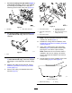
InstallingtheRollerBrush
Partsneededforthisprocedure:
318-inchRollerbrushhousing
222-inchRollerbrushhousing
10
Hex-socketbolt(3/8x1inch)
118-inchRightrollerbrushassembly
122-inchRightrollerbrushassembly
2
18-inchLeftrollerbrushassembly
1
22-inchLeftrollerbrushassembly
5
Shoulderbolt
1
18-inchRightbeltcover/plateassembly
1
22-inchRightbeltcover/plateassembly
2
18-inchLeftbeltcover/plateassembly
1
22-inchLeftbeltcover/plateassembly
10
Bolt(5/16x5/8inch)
3
Spacer
318-inchDrivepulley
222-inchDrivepulley
3
Flangeheadbolt(3/8x11/4inches)
2
Flangeheadbolt(3/8x2inches)
318-inchBelt
222-inchBelt
5
ShimWasher(Asrequiredforbeltalignment)
1
18-inchRightdriveshaft
1
22-inchRightdriveshaft
2
18-inchLeftdriveshaft
1
22-inchLeftdriveshaft
5
90°greasetting
1Bumperassembly
4
Bolt(1/4x2inches)
2
Brushshaftspacer
2Drivenpulleyspacer
2Drivenpulley
2
Flangenut(3/8inch)
122-inchRuler
Procedure
1.Parkthetractionunitonalevelsurfaceand
engagetheparkingbrake.
2.Ensurethatthecuttingunitsaredisengaged.
3.Turntheengineoffandremovethekey.
4.Removeallcuttingunitsfromthetractionunit.
Important:Checkthecuttingunitfor
desiredheight-of-cutandattitude.Reset
perOperator’sManual,ifrequired,before
installingRearRollerBrushKit.
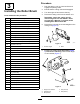
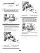
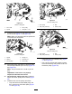
5.Removethenutsandthecounterweightsonthe
cuttingunit(Figure2).
g021340
Figure2
1.Counterweight
2.Bolts
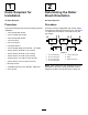
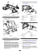
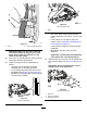
6.For22inchcuttingunits(#2and#3(Figure
1)rollerbrushsideonly).Removetheheight
ofcutbrackets(Figure3).
g021339
Figure3
1.Heightofcutbracket4.Nut(remove)
2.Carriagebolt5.Nut(loosen)
3.Nut(loosen)
4