
Operator's Manual
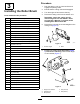
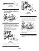
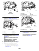

7.For22inchcuttingunits(#2and#3(Figure1)
rollerbrushsideonly).Removethesideplate
byremovinganyhardwareinthewayand
looseningtherearrollerclampnuts(Figure4).
g021341
Figure4
1.Sideplate
2.Rearrollerclampnut
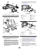
8.For22inchcuttingunits(#2and#3(Figure
1)rollerbrushsideonly).Removeboltsfrom
sideplate.
g021342
Figure5
1.Bolt
9.For22inchcuttingunits(#2and#3(Figure
1)rollerbrushsideonly).Installthesideplate
andheightorcutbracketbackontothecutting
unit.
10.Restrainthecuttingreelforremoval;referto
RestrainingtheReelforRemovingThreaded
Inserts(page14).
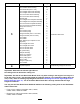
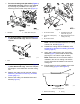
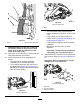
11.Removethecuttingunitthreadedinsertand
discard(Figure6).
g021425
Figure6
1.18-inchdriveshaft4.Threadedinsert(Left
inserthasringonit)
2.Apply242Loctite(blue)
here
5.Boltsremovedon22inch
cuttingunitsonly
3.22-inchdriveshaft
Note:Left-handthreadedinsertsareoncutting
units#1,#3,and#5(Figure1).
12.Restrainthecuttingreelforinstallation;refer
toRestrainingtheReelforInstallingThreaded
Inserts(page15).
13.Apply242Loctite(blue)tothedriveshaft
threads(Figure6)andinstallthedriveshaft,
torquingitto115–128N⋅m(85–95ft-lbs).
Note:Makesurethe18-inchdriveshaftis
installedinthe18–inchcuttingunitandthe
22-inchdriveshaftisinstalledinthe22–inch
cuttingunit
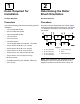
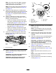
14.EnsurethattheO-ringisinstalledontheroller
brushhousing(Figure7andFigure8).
g020371
Figure7
18-inchcuttingunit
1.Rollerbrushhousing
2.O-ring
5