
Operator's Manual

g020394
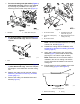
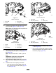
Figure8
22-inchcuttingunit
1.O-ring
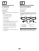
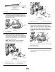
15.Onthe18-inchcuttingunitonly,remove
thestraightgreasettingneartherollerbrush
housingandinstallthe90°greasettinginthe
samespot(Figure9).
g020284
Figure9
1.90°greasetting
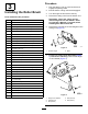
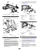
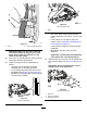
16.Mounttherollerbrushhousingtothereel
bearinghousingwith2hex–socketBolts(3/8x
1inch)(Figure10andFigure11).Positionthe
rollerbrushhousingsothattheO-ringisfacing
towardsthecuttingunit.
Note:MakesuretheO-ringisproperly
positionedintherollerbrushhousing.
g221549
Figure10
18-inchcuttingunit
1.Rollerbrushhousing
3.Cuttingunitboltsinstalled
2.Threadedholeinhousing4.Hex-socketbolts
g021427
Figure11
22-inchcuttingunit
1.Rollerbrushhousing
2.Cuttingunitboltsremoved
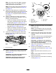
17.Removethe2angelocknutssecuringeach
rollerbrackettothesideplates(Figure12).
Note:Donotremovethebolts.Also,remove
any6mm(1/4inch)spacerspositioned
onthetopsideofthesideplatemounting
ange.
g020286
Figure12
1.Removethenutssecuring
eachendoftheroller.
3.Sideplatemountingange
2.6mm(1/4inch)spacer
18.Positiontheleftorrightrollerbrushassembly
mountingbracketsontotherollerbracketbolts
(Figure13).
6