
Operator's Manual

g021404
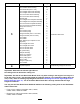
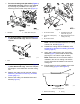
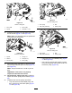
Figure13
1.Leftrollerbrushassembly
2.Rollerbrushmounting
bracket
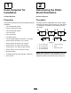
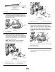
19.Slideeachexcludersealoutwarduntilthelip
sealsareinlightcontactwitheachbearing
housing(Figure14).
g020289
Figure14
1.Excluderseal2.Bearinghousing
20.Securethebrushassemblymountingbrackets
tothecuttingunitsideplateswiththenuts
previouslyremoved.
Important:Therollerbrushassembly
mountingbracketsmustbemounteddirectly
tothetopsurfaceofthecuttingunitside
platemountingange.Donotputspacers
betweentherollerbrushmountingbrackets
andthesideplatemountinganges.Save
theadditional6mm(1/4inch)spacersfor
potentiallateruse.
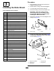
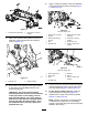
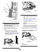
21.Applyacoatingofgreasetotheinnerdiameter
ofthegrommetinthebearinghousing(Figure
15andFigure16).
g021428
Figure15
18-inchcuttingunit
1.Roller-brushmounting
bracket
5.Roller-brushpivotplate
assembly
2.Roller-brushbearing
housing
6.Grommetinbearing
housing
3.Bolt7.Flangelocknuts
4.Shoulderbolt8.Cleanoutpaintfrom
threads
g021429
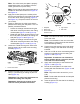
Figure16
22-inchcuttingunit
1.Brushshaftspacer
5.Washers
2.Brushplate
6.Spacer
3.Bolts
7.Cleanoutpaintfrom
threads
4.Shoulderbolt
22.Loosenbutdonotremovetheboltssecuringthe
rollerbrushbearinghousingtotherollerbrush
mountingbracket(Figure15andFigure16).
23.Onthe22-inchcuttingunitonly,slidethe
brushshaftspacerintoplace(Figure16).
24.Installtheleftorrightrollerbrushpivotplate
(Figure15andFigure16).
Note:Whentheprotrusiononthepivotplate
isinsertedintothegrommetinthebearing
housing,ensurethatthegrommetstaysproperly
seatedinthehousing.
7