
Operator's Manual

g020294
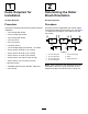
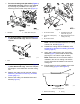
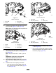
Figure19
18-inchcuttingunit
1.Driveshaft
3.Drivepulley
2.Spacer4.Bolt(3/8x1-1/4”)
34.Insertthedrivepulleyintothespacerandonto
thedriveshaft(Figure19andFigure20).
Note:Makesurethepulleytabsarepositioned
intheslotinthedriveshaft.
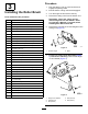
g021349
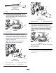
Figure20
22-inchcuttingunit
1.Spacer
4.Flangenut
2.Washer
5.Bolt(3/8x2”)
3.Drivenpulley6.Drivepulley
35.Securethepulleyandspacertothedriveshaft
withaangeheadbolt(3/8x2inch)(Figure19
andFigure20).
Note:Torquetheboltto47–54N⋅m(35–40
ft-lb).
Important:Iftheboltisnotproperly
torqued,theboltwillcomeloose.
36.Onthe22-inchcuttingunitsonly,installthe
spaceranddrivenpulleywithalocknut(Figure
20).
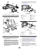
37.Installthebeltontothepulleysasfollows:
•Loopthebeltaroundthedrivepulleyand
thenoverthetopoftheidlerpulley(Figure
21andFigure22).
g020295
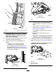
Figure21
18-inchcuttingunit
1.Drivepulley3.Belt
2.Idler-pulleyassembly4.Drivenpulley
g021350
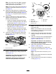
Figure22
22-inchcuttingunit
1.Drivepulley3.Belt
2.Idler-pulleyassembly4.Drivenpulley
•Installthebeltonthedrivenpulley(Figure
21andFigure22).
•Usea9/16inchdeep-wellsockettorotate
thebrushassemblyandguidethebeltonto
thedrivenpulley(Figure23).
9