
Installation Instructions
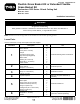
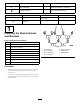
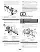
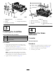
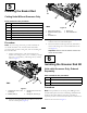
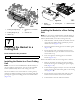
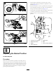


Figure11
8
AdjustingtheBasketPosition
NoPartsRequired
Procedure
Makesurethatthebasketisparalleltothecuttingunitor
slightlyraisedinfrontwithaminimumclearanceof6mm
(1/4inch)betweenthelipofthebasketandthereel,anda
minimumclearanceof6mm(1/4inch)betweenthefront
rollerandthebottomofthebasket.Toadjustthebasket
position,proceedasfollows:
•Oneachsideofthebasket,loosenthenutsonthe
carriageboltssecuringthebasket-stopbracketstothe
basket(Figure12).
•Positionthebasketsothatitisparalleltothecuttingunit
withaminimumclearanceof6mm(1/4inch)between
thelipofthebasketandthereel(Figure12).
•Oneachsideofthebasket,adjustthebasket-stopbrackets
sothattheyeachcontactacarrier-framearm.
•Tightenthenutsonthecarriageboltstosecurethebasket
position.
Figure12
1.6mm(1/4inch)clearance5.Contactpoint
2.Basket-stopbracket6.Roller
3.Basket
7.6mm(1/4inch)clearance
4.Carrier-framearm
7