
Operator's Manual

1
All Rights Reserved
Printed in the USA
1992, 2003 by The Toro Company
8111 Lyndale Avenue South
Bloomington, MN 55420-1196
Grooming Reel Kit
Greensmaster
1000
Model No. 04125
Form No. 3315–139
Operator’s Manual
Loose Parts Chart
DESCRIPTION QTY. USE
Frame Assembly R.H. 1 Attaches to right frame
Frame Assembly L.H. 1 Attaches to left frame
Bearing Adapter 2 Connects groomer to reel frame
Spacers 4 Connects groomer to reel frame
Slot Cover 2
Mount between groomer housing and left reel
bearing housing
Flat Head Screws 2 Fastens bearing adapters
Locknut 4 Fastens bearing adapters
Grooming Reel Assembly 1 41 blades, 1/2” spacing
Driven Pulley 1 Mounts to grooming reel
Locknut 1 Mounts to grooming reel
Clutch Assembly 1 Drives belt
Belt 1 Drives grooming reel
Ring Adapter 2 Connects groomer to reel frame
Operators Manual 1 Read before operating machine
Parts Catalog 1
Registration Card 1 Fill out and send to the Toro Co
Set–up Instructions
Important Read this Operator’s Manual thoroughly
before setting up or operating the groomer. Failure to
follow set up or operating instructions in this manual may
result in damage to the machine and/or the groomer or the
turf.
Note: Terms “left” and “right” are used in the text to refer
to left and right sides of the machine as viewed from the
operator’s position.
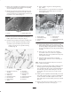
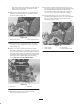
1. Loosen carriage bolts, washers, and locknuts securing
roller adjusting screws to height–of–cut brackets
(Fig. 1).
2. Loosen height–of–cut adjusting knobs until roller and
adjusting screws slide out of height–of–cut brackets
(Fig. 1).
Figure 1
1. Roller adjusting screw 2. Adjusting knob