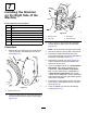
Form No. 3421-620 Rev A Groomer Drive System Fixed Head Greensmaster® Walk Behind Series Mowers Model No. 04134 Installation Instructions WARNING CALIFORNIA Proposition 65 Warning This product contains a chemical or chemicals known to the State of California to cause cancer, birth defects, or reproductive harm. Important: Read these instructions thoroughly before setting up or operating the groomer.
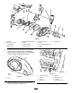
Procedure 7 8 Description Use Qty. Bearing Adapter Spacer Groomer-plate assembly Adapter ring Bolt (1/4 x 3-3/4 inches) Star washer Fastener retainer Weight Shaft clamp Bolt (1/4 x 1-1/4 inches) Jam nut Groomer reel (obtain separately) 1 2 1 1 2 2 2 1 4 4 4 1 Install the groomer on the right side of the machine. Install the grooming reel. 1 Preparing the Machine No Parts Required Procedure 1. Park the machine on a level surface. 2. Engage the parking brake. 3.
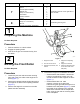
5. Install the height-of-cut arms as follows: 3 • Greensmaster 1600 mowers—obtain 2 new height-of-cut arms from your authorized Toro distributor and install them onto the roller assembly and side plates with the fasteners removed previously (Figure 2). Installing the Groomer Housing • Greensmaster 800 and 1000 mowers—rotate the height-of-cut arms you removed previously to the forward position and install them onto the roller assembly and side plates with the fasteners removed previously (Figure 2).
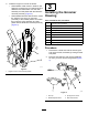
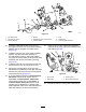
3. 4. If you are installing this kit on a Greensmaster 800 mower with a serial number prior to 230999999, a Greensmaster 1000 mower with a serial number prior to 229999999, or a Greensmaster 1600 mower with a serial number prior to 260001401, complete the following: A. Remove the 40-tooth idler gear. Using a 7/8 inch standard wrench, loosen the spring tension screws on the right and left bedbar adjusters (Figure 4). g022023 Figure 5 1. 40-tooth idler gear. 5. g020979 Figure 4 1.
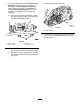
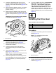
g245796 Figure 6 1. Locknut 5. Adjustment knob assembly 13. Adapter ring 9. Groomer housing 2. Bolt (3/8 x 5/8 inch) 6. Spacer 10. O-ring 3. Curved washer 7. Bearing adapter 11. Slot cover (flat edge down) 4. Mounting block 8. Flat-head screw 12. Gasket 6. Install the O-ring into the back of the groomer housing (Figure 6 and Figure 7) and lightly lubricate the exposed surfaces of the O-ring with synthetic grease (supplied with the kit). g020844 Figure 8 g020843 Figure 7 1. O-ring 7.
8. Insert the 2 flat-head screws (3/8 x 2 inch) through the bearing adapter and position the spacers on the ends of the screws (Figure 6 and Figure 8). 9. Align the bearing adapter, spacers, and screws with the bronze bushing and the slots in the groomer housing. 10. Slide the bearing adapter through the bronze bushing and the screws through the slots in the groomer housing assembly (Figure 6 and Figure 8). 16.
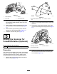
g022024 Figure 11 1. Shaft assembly 3. Groove 2. Drive gear 4. 40-tooth idler gear 4. g020880 Figure 12 1. Socket-head bolts—keep one Secure the reel from turning with a wood block and torque the shaft assembly to 54 to 81 N∙m (40 to 60 ft-lb). 5. Apply synthetic grease (supplied with the kit) to the male spline of the shaft assembly (Figure 11). 6. Slide the drive gear with the groove oriented outward onto the shaft assembly (Figure 11). 7. Install the 40-tooth idler gear (Figure 11). 2.
6 Installing the Groomer-Housing Cover Parts needed for this procedure: 1 Groomer-housing cover assembly 1 Gasket 5 Flange-head bolt (1/4 x 3/4 inch) 1 Synthetic grease (3.0 oz) g020882 Figure 14 Procedure 1. Socket-head bolt previously removed from the cover 5. Press fit the center gear removed previously onto the hub (Figure 15). 1. Coat the teeth of the gears with the synthetic grease supplied with the kit. Use the remaining grease to fill in the area around the gears. 2.
7 Installing the Groomer on the Right Side of the Machine Parts needed for this procedure: 1 Bearing Adapter 2 Spacer 1 Groomer-plate assembly 1 Adapter ring 2 Bolt (1/4 x 3-3/4 inches) 2 Star washer 2 Fastener retainer 1 Weight g017185 Figure 18 1. Reel drive belt 3. Drive pulley 2. Idler pulley 4. Flat-head screw 3. Procedure 1. Note: The drive pulley has right-hand threads.
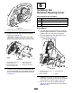
g020847 Figure 19 1. Flat-head screw 4. Spacer 7. Bolt 2. Groomer arm cover 5. Adjustment-knob, mounting block 8. Adapter ring 3. Bearing adapter 6. Curved washer 9. Groomer-plate assembly 10. Insert the 2 flat-head screws (3/8 x 2 inch) through the groomer arm cover and the bearing adapter and put a spacer over each screw (Figure 19). 11.
17. Torque the pulley to 54 to 81 N∙m (40 to 60 ft-lb). 18. Install reel drive belt and check the belt tension by pressing the belt at the mid span of the pulleys with 1.5 to 2.5 kg (3 to 5 lb) of force. 8 Installing the Grooming Reel The belt should deflect 6 mm (1/4 inch). Reposition the idler pulley to adjust the belt tension. Tighten the screws once you achieve the proper tension. 19.
3. Slide the groomer-reel shaft into the clamp on the right side and swing it up to the drive shaft on the left (Figure 22). 6. Correct any problems and check the assembly. 7. Using a hand-pump grease gun, lubricate the 2 groomer-shaft bearings (1 on each end). Important: If installing a carbide-toothed Note: Pump only 2 to 3 pumps maximum to avoid permanently damaging the grease seals. groomer, ensure that the teeth point in the direction the groomer will rotate when installed. 8.
Operation • The type of grass on the green • The overall greens management program (i.e., irrigation, fertilizing, spraying, coring, overseeding, etc.) Introduction • Traffic Grooming is performed in the turf canopy above the soil level. Grooming promotes vertical growth of grass plants, reduces grain, and severs stolons, producing a denser turf. Grooming produces a more uniform and tighter playing surface for faster and truer action of the golf ball. • Stress periods (i.e.
Testing the Groomer Performance of the turf (along with close examination) if the current grooming practice is appropriate for the particular green. Because the groom reel stands up more grass and removes thatch, the quality of cut is not the same as without the groomer. This effect is most noticeable the first few times that you use a groomer on a green. Important: Improper or over-aggressive use of the grooming reel (i.e.
Turning the Groomer On and Off You can turn the groomer on or off by rotating the groomer-drive clutch as shown in Figure 27. g017190 Figure 26 4. Lift and turn the micro adjustment knob (Figure 25) to raise or lower blade tip. g020855 Note: Each notch on the micro adjustment Figure 27 knob is approximately equal to 0.17 mm (0.007 inch) of groomer depth. 5. Repeat this procedure on the opposite end of the groomer, then recheck the setting on the first side. 6.
Maintenance Replacing the Grooming Reel Cleaning Remove and replace the grooming reel using the following procedure: Hose off the grooming reel after use. Do not direct the water stream directly at the groomer bearing seals. Do not permit the grooming reel to stand in water so that the components rust. 1. Remove both bolts, nuts, and shaft clamps from one side of the groomer reel (Figure 23). 2. Remove the inner bolt from the clamp on the other side and loosen the outer bolt.
Notes:
Notes:
Notes:
Declaration of Incorporation The Toro Company, 8111 Lyndale Ave. South, Bloomington, MN, USA declares that the following unit(s) conform(s) to the directives listed, when installed in accordance with the accompanying instructions onto certain Toro models as indicated on the relevant Declarations of Conformity. Model No. 04134 Serial No.