
Installation Instructions

1
All Rights Reserved
Printed in the USA
W 2004 by The Toro Company
8111 Lyndale Avenue South
Bloomington, MN 55420-1196
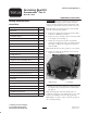
Grooming Reel Kit
Greensmaster
)
Flex 21
Model No. 04204
Form No. 3353–598 Rev. A
Installation Instructions
Setup Instructions
Loose Parts
Description Qty.
Plow bolt 2
Shim 1
Sideplate adapter 2
Oil seal 1
Groomer drive assembly (R.H.) 1
Lock nut 2
Drive pulley 1
Driven pulley 1
Square key 1
Flange lock nut 2
Bushing 2
Height of cut arm assembly (R.H.) 1
Capscrew–M6 2
Spring washer 2
Locknut 2
Locknut 2
Groomer housing assembly (L.H.) 1
Bearing 2
Cap plug 1
Shift lever spring 1
Height of cut arm assembly (L.H.) 1
Belt 1
Cover 1
Installation Instructions 1
Parts catalog 1
Important Read these instructions thoroughly before
setting up or operating the groomer. Failure to follow
setup or operating instructions in this manual may result
in damage to the machine and/or the groomer or the turf.
Note: Determine the left and right sides of the machine
from the normal operating position.
1. Separate the cutting unit from the traction unit. Refer
to Operator’s Manual for procedure.
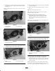
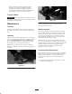
2. Loosen the screws securing each end of the front roller
to the height-of-cut arms (Fig. 1).
3. Remove the carriage bolts, washers and locknuts
securing the height-of-cut arms to the cutting unit side
plates (Fig. 1). Remove the height-of-cut arms and
roller assembly.
Note: Retain all parts for use if groomer is ever removed.
4. Remove the height-of-cut adjusting screws from the
height-of-cut arms (Fig. 1).
1
2
Figure 1
1. Height of cut arm 2. Reel weight
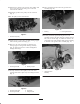
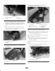
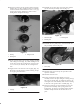
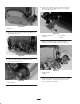
5. Remove the front bolt securing the bearing housing to
the sideplate (Fig. 2). Replace with new shorter plow
bolt (Fig. 3).
Note: On cutting units with serial numbers prior to
219999999, enlarge the front sideplate hole to .413”. This
will ease the installation of the new larger plow bolt.
Note: Replace one bolt at a time to retain the position of
the reel bearing housing.