
Operator's Manual

10
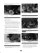
1
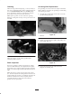
Figure 35
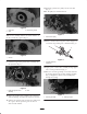
1. Roller shaft bolt
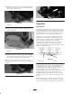
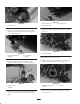
4. Remove the locknut and spring washer securing the
height-of-cut arm assembly rod end to the groomer
drive assembly (Fig. 36).
1
2
3
Figure 36
1. Rod end of height of cut
assembly
2. Spring washer
3. Locknut
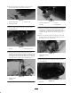
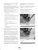
5. Remove carriage bolt, nut, and washer securing
height-of-cut arm assembly to side plate (Fig. 37).
1
Figure 37
1. Height of cut arm
assembly
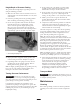
6. Remove the flange lock securing the driven pulley to
the end of the groomer shaft (Fig. 38). Remove the
pulley.
1
2
3
Figure 38
1. Groomer driven pulley
2. Grooming reel shaft
3. Flange lock nut
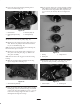
7. Remove the groomer drive pulley from the reel shaft
(Fig. 39).
1
Figure 39
1. Groomer drive pulley
Note: The nut has left-hand threads.
8. Remove the (2) locknuts securing the groomer drive
assembly to the side plate capscrews (Fig. 40).
1
2
2
Figure 40
1. Right hand groomer drive
assembly
2. Locknuts
9. Remove the groomer drive assembly from the side
plate capscrews.