
Operator's Manual

3
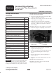
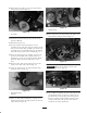
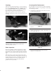
16. Loosely mount the driven pulley to the end of the
groomer shaft with a flange lock nut (Fig. 8).
1
2
3
Figure 8
1. Groomer driven pulley
2. Grooming reel shaft
3. Flange lock nut
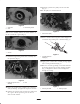
17. Insert a bushing into the hole in the groomer drive
assembly (Fig. 9).
2
1
Figure 9
1. Bushing 2. Hole in groomer drive
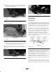
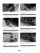
18. Loosely install the right-hand height-of-cut arm
assembly onto the side plate using the existing carriage
bolt, nut, and washer (Fig. 10). Make sure that the rod
end height-of-cut arm assembly slides into the bushing
in the hole in the groomer drive assembly (Fig. 11).
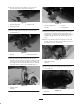
1
Figure 10
1. Height of cut arm
assembly
1
2
3
Figure 11
1. Rod end of height of cut
assembly
2. Locknut
3. Spring washer
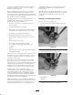
19. Secure the height-of-cut arm assembly rod end to the
groomer drive assembly with a spring washer and
locknut (Fig. 11). Do not overtighten locknut. Washer
should be compressed but the arm must be free to
pivot.
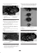
20. Insert the roller shaft into the height-of-cut arm and
loosely secure with a M6 capscrew (Fig. 12). Do not
install belt and cover at this time.
1
Figure 12
1. Roller shaft mounting
capscrew
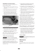
21. On the left end of the cutting unit, remove the belt
cover (Fig. 13).
1
Figure 13
1. Belt cover