
Operator's Manual

4
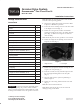
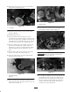
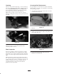
22. Loosen the (2) bearing housing mounting nuts to
relieve belt tension (Fig. 14).
3
1
4
2
2
4
4
Figure 14
1. Reel drive belt
2. Bearing housing mounting
nuts
3. Reel drive pulley nut
4. Mounting bolts (3)
23. Remove the belt from the pulleys (Fig. 14).
24. Remove the nut securing the drive pulley to the reel
shaft. Remove the pulley from the shaft. Retain the
key for re–installation (Fig. 14).
Note: To prevent reel from turning when removing nut,
block reel with a piece of wood.
25. Remove the (2) nuts and the bolt securing the reel
drive plate to the side plate (Fig. 14). Remove the
drive plate assembly.
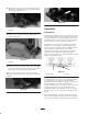
Note: Do not remove the ring spacer from the bearing
housing.
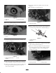
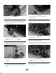
26. Slide the groomer housing assembly onto the ring
spacer and groomer shaft (Fig. 15).
1
Figure 15
1. Groomer housing assembly
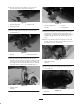
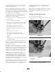
27. Insert the bearings onto the groomer shaft in groomer
housing (Fig. 16). The extended bearing races should
contact each other when installed to create a 1/4” gap
between the bearings. Support the shaft to reduce
misalignment through the bearings.
28. Secure groomer shaft to the groomer housing assembly
with a flange lock nut (Fig. 16). While holding the nut
on the other end of the groomer shaft, torque the nuts
to 17–21 ft.-lb. (23–28 N⋅m). Do not overtighten the
nuts.
1
2
2
1
3
Figure 16
1. Bearing
2. Bearing race
3. Flange lock nut
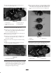
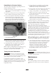
29. Reinstall the reel drive plate to the side plate with the
(2) nuts and bolt previously removed (Fig. 17).
2
1
2
Figure 17
1. Reel drive plate 2. Mounting nuts