
Operator's Manual

5
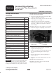
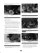
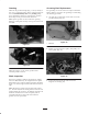
30. Reinstall the drive pulley w/key to the shaft with the
nut previously removed (Fig. 18).
1
Figure 18
1. Drive pulley
31. Install the belt and tension per the procedure in the
Operator’s Manual.
32. Install the left belt cover.
33. Loosely install the left-hand height-of-cut arm
assembly onto the side plate using the existing carriage
bolt, nut, and washer (Fig. 10). Make sure that the rod
end height-of-cut arm assembly slides into the bushing
in the hole in the groomer drive assembly (Fig. 11).
34. Secure the height-of-cut arm assembly rod end to the
groomer drive assembly with a spring washer and
locknut (Fig. 11). Do not overtighten locknut. Washer
should be compressed but the arm must be free to
pivot.
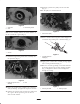
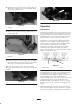
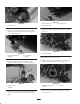
35. Insert the roller shaft into the height-of-cut arm and
loosely secure with a M6 capscrew (Fig. 19).
36. Center the roller between the arms and tighten both
mounting capscrews (Fig. 19).
1
Figure 19
1. Roller shaft mounting
capscrew
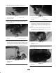
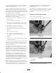
37. Rotate the idler pulley until shift lever spring can be
hooked into the hole in the pulley bracket and onto the
stud as shown in figure 20.
1
Figure 20
1. Shift lever spring
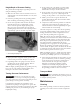
38. Insert the belt onto the driver pulley, idler pulley and
driven pulley routing as shown in figure 21.
Figure 21
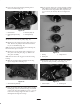
Important Make sure the belt is centered on the
pulleys and in the grooves (Fig. 22).
Figure 22
39. Set reel HOC by adjusting the front roller position. Set
groomer HOC. Rotate reel by hand to make sure the
groomer shaft is seated properly in the bearings and
the belt is tracking straight. Double check the torque
setting on both ends of the groomer shaft. Refer to
step 28 for the torque specification.