
Installation Instructions
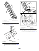
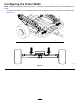

g341267
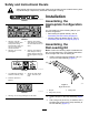
Figure7
1.Spring
2.Bolt
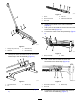
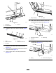
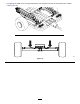
11.Use10hex-headscrewstosecurethechain
coverstotherampassemblies(Figure8).
g342431
Figure8
1.Hex-headscrew
2.Chaincover
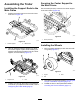
Assemblingthe
Wheel-LoadingKit
Note:Performthefollowingstepstoassemblethe
left-andright-sidedwheelramps.Thefollowing
illustrationsshowtherightsideofthewheel-loading
kit.
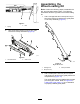
1.Use2carriageboltsand2nuts(5/16inch)to
securethelatch-pinbrackettotheguideplate
ontherampassembly(Figure9).
g338531
Figure9
Rightsideshown.
1.Carriagebolt
3.Latch-pinbracket
2.Nut(5/16inch)
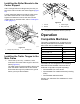
2.Use10bolts(5/16x3/4inch)and10nylock
nuts(5/16inch)tosecuretheguideplatetothe
rampassembly(Figure10).
Theguideplatesmustbeinstalledwiththelatch
pinsfacingtheoutside.RefertoFigure30in
LoadingtheTrailer(page11)foranillustration
ofproperlyinstalledguideplates.
4