Form No. 3390-846 Rev C Forward-Rotating Groomer Drive System-Greensmaster Flex™ 1800/2100 and eFlex® 1800/2100 Mower Model No. 04259 Installation Instructions • 21-inch stiff grooming brush The following groomer reels are also available for this product: • • • • • • • • • • • 21-inch thin spring steel groomer 18-inch carbide groomer Contact your Authorized Toro Distributor for more information.
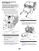
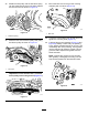
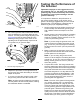
Installing the Groomer Drive System Important: Read these instructions thoroughly before setting up or operating the groomer. Failing to follow setup or operating instructions in this manual may result in damage to the cutting unit and/or the groomer or the turf. Note: Determine the left and right sides of the machine from the normal operating position. G016289 1. Separate the cutting unit from the traction unit. Refer to the Operator's Manual for procedure. 2 2.
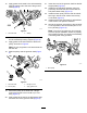
2 1 g028128 g017633 Figure 6 g017663 Figure 4 1. Lower pulley 1. Compression spring 2. Set screw 2. Inner and outer compression spring 12. Slide the shim plate onto the rear of the right drive assembly as shown in Figure 7. 10. Remove the 3 bolts securing the belt drive assembly to the cutting unit and remove the whole assembly (Figure 5). G027980 g017664 5 4 1 1 2 3 g017664 Figure 5 1. Left support plate 3. Bolts 2. Belt drive assembly 2 3 g027980 Figure 7 11.
21. Insert other end of the groomer shaft into the left support plate (Figure 5). 15. Apply grease to the seals in the drive assembly bearing support and to the end of the groomer shaft (Figure 8). 22. Install the reel belt-drive assembly using the previously removed bolts and ensure that the side plate rotates freely (Figure 5). 23. Install the lower pulley onto the reel drive shaft, securing it with the 2 set screws onto the key on the shaft (Figure 4). 24.
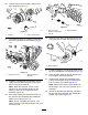
26. Insert a bushing into the hole in the groomer drive assembly (Figure 11). 1 3 2 2 1 g016217 Figure 13 G016215 1. Rod end of the height-of-cut assembly g016215 Figure 11 1. Bushing G016217 3. Belleville washer 2. Locknut 2. Hole in groomer drive 30. Insert the roller shaft into the right adjuster arm and loosely secure it with the bolt (Figure 14). 27. Thread the height-of-cut adjusting screw into the top of the right adjuster arm assembly (Figure 12). 1 2 G016229 g016229 Figure 14 1.
35. Rotate the idler pulley until the shift lever spring can be hooked into the hole in the pulley bracket and onto the stud as shown in Figure 15. 37. Mount the belt cover to the groomer housing assembly with 3 locknuts (Figure 18). G016233 G016230 g016233 Figure 18 g016230 Figure 15 1. Belt cover 1. Shift lever spring 38. Center the roller between the adjuster arms and tighten the mounting bolts (Figure 14). 36.
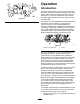
Operation Introduction Grooming is performed in the turf canopy above the soil level. Grooming promotes vertical growth of grass plants, reduces grain, and severs stolons producing a denser turf. Grooming produces a more uniform and tighter playing surface for faster and truer action of the golf ball. g010436 Figure 20 Verticutting is a more aggressive cultivation technique designed to remove thatch by cutting through the turf canopy and into the thatch/mat layer.
• The general condition of each green • The frequency of grooming/cutting-both how many cuttings per week and how many passes per cutting • The height-of-cut setting on the main reel • The height/depth setting on the grooming reel • How long the grooming reel has been in use on this green • The type of grass on the green • The overall greens management program (i.e. irrigation, fertilizing, spraying, coring, over seeding, etc.) • Traffic • Stress periods (i.e.
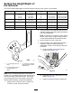
Setting the Height/Depth of the Groomer The groomer blade height/depth can be set using the following chart, figures, and procedure: Rear Roller Spacers Required Height-of-Cut (mm) 0 1.5 3.0 4.8 6.3 1 mm mm mm mm Height-of-Cut (inches) 0.06 0.12 0.19 0.25 Groomer Arm Position Height-of-Grooming Range (mm) to to to to 1.5 3.0 4.8 6.3 Height-of-Grooming Range (inches) inches inches inches inches A A B B 0.7 1.5 2.2 3.0 mm mm mm mm 0.03 to 0.06 inches 0.06 to 0.12 inches 0.09 to 0.19 inches 0.
Testing the Performance of the Groomer Important: Improper or over-aggressive use of the grooming reel (i.e., too deep or too frequent grooming) may cause unnecessary stress on the turf leading to severe greens damage. Use the groomer cautiously. It is important to determine the performance of the groomer before putting it into regular use on greens. We strongly suggests that you use a formal test procedure. The following is a practical way of determining the proper height/depth setting: g016235 1.
Maintenance Note: On multiple passes (i.e., double and triple cutting), the groomer will continue to penetrate deeper on each successive pass. Multiple passes are not recommended. Cleaning the Grooming Reel 5. After you test the performance of the groomer on a test green and obtain satisfactory results, you can begin grooming on the playing greens. However, each green may respond differently to grooming. In addition, growing conditions are constantly changing.
Inspecting the Blades Replacing the Grooming Reel Inspect the grooming-reel blades frequently for damage and wear. Straighten bent blades with a pliers. Replace worn blades; torque the lock nuts to 42 to 49 N·m (31 to 36 ft-lb). When inspecting the blades, check to see that the right and left blade shaft end nuts are tight. You can remove the grooming reel to replace individual blades or the entire shaft. Remove and replace the grooming reel shaft using the following procedure: 1.
1 2 G016229 g016229 Figure 31 1. Roller shaft bolt 4. Remove the locknut and Belleville washer securing the height-of-cut arm assembly rod end to the groomer drive assembly (Figure 32). G016258 g016258 Figure 33 1. Right adjuster arm assembly 2. Washer and locknut 6. Remove the flange locknut securing the driven pulley to the end of the groomer shaft (Figure 34). Remove the pulley. g010439 Figure 32 1. Rod end of height of cut assembly 3. Locknut 2. Belleville washer 5.
1 G16239 g016239 Figure 35 1. Groomer drive pulley 8. Remove the 2 shoulder bolts securing the groomer drive assembly to the side plate adapters (Figure 36). G016240 g016240 Figure 36 1. Groomer drive assembly 2. Shoulder bolts 9. Remove the groomer drive assembly from the bolts. 10. Remove the groomer shaft. 11. Torque the groomer drive pulley to 170 N·m (125 ft-lb). Note: The use of an impact gun is not enough to ensure proper installation.
Notes:
Declaration of Incorporation The Toro Company, 8111 Lyndale Ave. South, Bloomington, MN, USA declares that the following unit(s) conform(s) to the directives listed, when installed in accordance with the accompanying instructions onto certain Toro models as indicated on the relevant Declarations of Conformity. Model No. 04259 Serial No.