
Installation Instructions
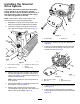

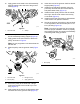
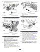
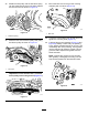
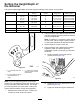
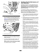
Table Of Contents

InstallingtheGroomer
DriveSystem
Important:Readtheseinstructionsthoroughly
beforesettinguporoperatingthegroomer.
Failingtofollowsetuporoperatinginstructionsin
thismanualmayresultindamagetothecutting
unitand/orthegroomerortheturf.
Note:Determinetheleftandrightsidesofthe
machinefromthenormaloperatingposition.
1.Separatethecuttingunitfromthetractionunit.
RefertotheOperator'sManualforprocedure.
2.Loosenthescrewssecuringeachendofthe
frontrollertotheheight-of-cutarms(Figure1).
G016224
g016224
Figure1
1.Rollermountingscrews
3.Carriagebolt,washer,and
locknut
2.Height-of-cutarm
4.Adjustingscrew
3.Removetheplowbolts,washers,andlocknuts
securingtheheight-of-cutarmstoeachendof
cuttingunit(Figure1).Removetheheight-of-cut
armsandrollerassembly.
Note:Retainallpartsforuseifthegroomeris
everremoved.
4.Removetheheight-of-cutadjustingscrewsfrom
theheight-of-cutarms(Figure1).
5.Removethe2boltsandnutssecuringthe
counterweighttotherightendofthecuttingunit.
Removethecounterweight(Figure2).
G016289
1
2
g016289
Figure2
1.Counterweight
2.Bearingnut
6.Removethebearingnutfromthereelshaft
(Figure2).
7.Loosenthecaptiveboltsecuringthebeltcover
totheleftendofthecuttingunituntilyoucan
removethecover(Figure3).
g017662
1
2
3
4
g017662
Figure3
1.Beltcoverbolt,captive3.Belt
2.Beltcover4.Belttensioningnut
8.Loosenthebelttensioningnutandremovethe
belt(Figure3).
9.Loosenthe2setscrewssecuringthelower
pulleyandremovethepulleyfromthereelshaft
(Figure4).
2