
Installation Instructions
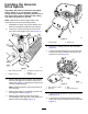

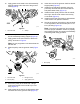
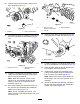
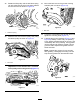
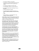
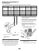
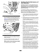
Table Of Contents

g017633
1
2
g017663
Figure4
1.Lowerpulley
2.Setscrew
10.Removethe3boltssecuringthebeltdrive
assemblytothecuttingunitandremovethe
wholeassembly(Figure5).
g017664
1
2
3
g017664
Figure5
1.Leftsupportplate
3.Bolts
2.Beltdriveassembly
11.Usealong-noseplierstoremovethe
compressionspringsonbothsidesofthecutting
unitandreplacethemwiththenewinnerand
outercompressionsprings(Figure6).
g028128
Figure6
1.Compressionspring
2.Innerandouter
compressionspring
12.Slidetheshimplateontotherearoftheright
driveassemblyasshowninFigure7.
1
2
3
4
5
G027980
g027980
Figure7
1.Rightdriveassembly
4.Shimplate
2.Shoulderbolt
5.Pilotbore
3.O-ring
13.PutalightcoatingofgreaseontheO-ringand
thepilotbore(Figure7).
14.Securethedriveassemblyusing2shoulder
boltsasshowninFigure7.
Note:Makesurethatthesideplaterotates
freely.
3