
Installation Instructions
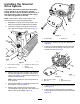

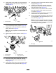
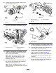
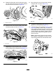
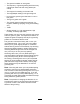
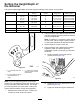
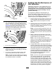
Table Of Contents

15.Applygreasetothesealsinthedriveassembly
bearingsupportandtotheendofthegroomer
shaft(Figure8).
G027981
2
g027981
Figure8
1.Groomershaft2.Seallip
16.Slidethesplinedendofthegroomershaftinto
thedrive-assemblybearingsupport(Figure8).
17.Applygreasetothesealsurfaceofthedriven
pulley,asshowninFigure9.
Note:Donotputgreaseontheareawherethe
beltwillride.
18.Slidethepulleyontothegroomershaft(Figure
9).
G016228
g016228
Figure9
1.Groomershaft
3.Flangelocknut
2.Drivenpulley4.Applygreasehere
19.Securethepulleytotheshaftwithaange
locknutandtorqueto23to28N·m(17to21
ft-lb)(Figure9).
20.Applygreasetothesealintheleftsupportplate
andtotheendofthegroomershaft(Figure9).
21.Insertotherendofthegroomershaftintotheleft
supportplate(Figure5).
22.Installthereelbelt-driveassemblyusingthe
previouslyremovedboltsandensurethatthe
sideplaterotatesfreely(Figure5).
23.Installthelowerpulleyontothereeldriveshaft,
securingitwiththe2setscrewsontothekey
ontheshaft(Figure4).
24.Installthedrivebeltandtensionitasdescribed
inthetractionunitOperator’sManual.
25.Securethegroomerdrivepulleytothereelshaft
ontherightsideofthereelandtorqueitto170
N·m(125ft-lb)(Figure10).
Note:Theuseofanimpactgunisnotenough
toensureproperinstallation.Failuretoproperly
torquethedrivepulleycanresultintheassembly
unscrewingitselfduringoperation.
1
G016218
g016218
Figure10
1.Drivepulley
4