
Installation Instructions
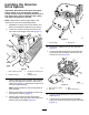

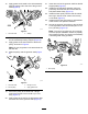
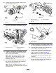
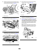
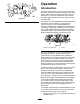
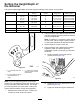
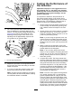
Table Of Contents

26.Insertabushingintotheholeinthegroomer
driveassembly(Figure11).
1
2
G016215
g016215
Figure11
1.Bushing2.Holeingroomerdrive
27.Threadtheheight-of-cutadjustingscrewintothe
topoftherightadjusterarmassembly(Figure
12).
1
2
G016216
g016216
Figure12
1.Height-of-cutscrew
2.Rightadjusterarm
assembly
28.Installtherightadjusterarmassemblytothe
cuttingunitsideplateusingtheexistingplow
bolt,nut,andanewwasher.
Note:Makesurethattherodendofthe
height-of-cutarmassemblyslidesintothe
bushingintheholeinthegroomerdrive
assembly(Figure12).
29.Securetheadjusterarmassemblyrodendto
thegroomerdriveassemblywithaBelleville
washerandlocknut(Figure13).
Note:Donotovertightenthelocknut.The
washershouldbecompressedbutthearmmust
befreetopivot.
1
2
3
G016217
g016217
Figure13
1.Rodendofthe
height-of-cutassembly
3.Bellevillewasher
2.Locknut
30.Inserttherollershaftintotherightadjusterarm
andlooselysecureitwiththebolt(Figure14).
G016229
g016229
Figure14
1.Rollershaftbolt
31.Threadtheheight-of-cutadjustingscrewintothe
topoftheleftadjusterarmassembly(Figure12).
32.Inserttherollershaftintotheleftadjusterarm.
Donottightentheboltatthistime.
33.Installtheleftadjusterarmassemblytothe
cuttingunitsideplateusingtheexistingplow
bolt,nut,andanewwasher(Figure12).
Note:Makesurethattherodendslidesinto
thebushingintheholeinthegroomerdrive
assembly.
34.Securetheadjuster-armassemblyrodendto
thegroomerdriveassemblywithaBelleville
washerandlocknut(Figure13).
5