
Operator's Manual


3
InstallingtheRollBar
Partsneededforthisprocedure:
2
Bolt(1/2x1-3/4inches)
6
Bolt(1/2x1-1/2inches)
8
Nut(1/2inch)
Procedure
1.Removethescrewsandnutssupportingthe
jackpadontherightsideofthemachine.
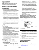
2.Lowertherollbar(Figure6)ontothemounting
brackets,aligningthemountingholes.
g213342
Figure6
1.Jackpad4.Rollbar
2.Bolt(1/2x1-3/4inches)5.Seatbelt
3.Bolt(1/2x1-1/2inches)
3.Securetheleftsideoftherollbartothemounting
bracketwith4bolts(1/2x1-1/2inches)and
locknuts(Figure6).
4.Torquethefastenersto91to115N∙m(67to85
ft-lb).
5.Securetherightsideoftherollbarandthe
previouslyremovedjackpadtothemounting
bracketwith2bolts(1/2x1-1/2inches),2bolts
(1/2x1-3/4inches),andlocknutsasillustrated
inFigure6.
6.Torquethefastenersto91to115N∙m(67to85
ft-lb).
WARNING
Failuretoweartheseatbeltwhileoperating
thevehiclecanresultinyoubeingthrown
fromtheseatandinjuredduringarollover
accident.
Alwaysusetheseatbelt.
4
InstallingtheCuttingUnits
Partsneededforthisprocedure:
3
Cuttingunit
3
Grassbasket
Procedure
Important:Donotraisethesuspensiontothe
transportpositionwhenthereelmotorsareinthe
holdersonthemachineframe.Damagetothe
motorsorhosescouldresult.
Note:Whensharpening,settingtheheightofcut,
orperformingothermaintenanceproceduresonthe
cuttingunits,storethecuttingunitreelmotorsinthe
supporttubesonthefrontoftheframeandsideofthe
machinetopreventdamagingthehoses.
1.Removethecuttingunitsfromthecartons.
Assembleandadjustthemaslistedinthecutting
unitOperator'sManual.
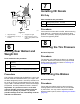
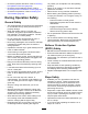
2.Slidethecuttingunitunderthepullframewhile
slidingthelifthookontotheliftarm(Figure7).
g005101
Figure7
1.Liftarm2.Lifthook
3.Slidethesleevebackontheballjointreceiver
andhookthereceiverontothecuttingunitball
stud.Releasethesleevesothatitslidesover
12