Form No. 3358-842 Rev B Greensmaster® 3250–D Traction Unit Model No. 04383—Serial No. 280000001 and Up Register at www.Toro.com.
Warning Model No. CALIFORNIA Proposition 65 Warning The engine exhaust from this product contains chemicals known to the State of California to cause cancer, birth defects, or other reproductive harm. Serial No. This manual identifies potential hazards and has safety messages identified by the safety alert symbol (Figure 2), which signals a hazard that may cause serious injury or death if you do not follow the recommended precautions.
Contents Recommended Maintenance Schedule(s) ................ 36 Daily Maintenance Checklist............................... 37 Lubrication............................................................. 38 Engine Maintenance............................................... 39 Servicing the Air Cleaner .................................... 39 Changing the Engine Oil and Filter ..................... 39 Adjusting the Throttle Control............................ 39 Adjusting the Idle Speed ..........................
Safety ◊ the type of machine is unsuitable for the task; ◊ lack of awareness of the effect of ground conditions, especially slopes. ◊ The owner/user can prevent and is responsible for accidents or injuries occurring to himself or herself, other people, or property This machine meets or exceeds CEN standard EN 836:1997, ISO standard 5395:1990, and ANSI B71.4-2004 specifications in effect at the time of production when 40 lb. of ballast is added to the rear wheel.
• Reduce the throttle setting before stopping the engine and, if the engine is provided with a fuel shut-off valve, turn the fuel off at the conclusion of mowing. • Keep hands and feet away from the cutting units. • Look behind and down before backing up to be sure of a clear path. • Slow down and use caution when making turns and crossing roads and sidewalks. Stop the reels when not mowing. • Do not operate the mower under the influence of alcohol or drugs.
• Disconnect battery before making any repairs. Disconnect the negative terminal first and the positive last. Reconnect positive first and negative last. • Use care when checking the reels. Wrap the reels or wear gloves, and use caution when servicing them. • Keep hands and feet away from moving parts. If possible, do not make adjustments with the engine running. • Charge batteries in an open well ventilated area, away from spark and flames. Unplug charger before connecting or disconnecting from battery.
Sound Power parking brake. Stop the engine and remove the key from the ignition switch. This unit has a guaranteed sound power level of 105 dBA, based on measurements of identical machines per ISO 11094. • Whenever the machine is left unattended, make sure the cutting units are fully raised, the reels are not spinning, the key is removed from the ignition switch, and the parking brake is set. Vibration Maintenance and Storage This unit does not exceed a hand/arm vibration level of 2.
Safety and Instructional Decals Safety decals and instructions are easily visible to the operator and are located near any area of potential danger. Replace any decal that is damaged or lost. 114–4614 93–8068 1. Read the Operator’s Manual for instructions on how to lock and unlock the steering arm. 93–9051 1. Read the Operator’s Manual. 108–5278 93–6681 1. Warning–read theOperator’s Manual. 1. Cutting/dismemberment hazard—stay away from moving parts. 93–6689 93–6686 1. Hydraulic oil 1.
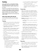
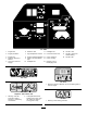
107–9529 1. Engine start 2. Engine preheat/on 6. Raise the reels 7. High temperature override 3. Engine stop 4. Read the Operator’s Manual. 5. Lower the reels and engage. 11. Headlights Off 12. Functional control lever 8. Engine coolant temperature 13. Use for transport 9. Water in the fuel indicator 14. Use for mowing light 10. Headlights On 15. Neutral—Use for backlapping reels 16. Throttle—slow 17. Throttle—continuous variable setting 18. Throttle—fast 104–7728 93–7275 1.
6–5976 1. Engine coolant under pressure 2. Explosion hazard—read the Operator’s Manual. 3. Warning –do not touch the hot surface. 4. Warning–read the Operator’s Manual. 93–8063 Replaces 104–2053 for CE. * This safety decal includes a slope warning required on the machine for compliance to the European Lawn Mower Safety Standard EN836:1997. The conservative maximum slope angles indication for operation of this machine are prescribed by and required by this standard. 1.
4–4615 1. 2. 3. 4. 5. 6. 7. 8. Height of cut 5 blade reel 8 blade reel 11 blade reel Battery Symbols Some or all of these symbols are on your battery. 1. Explosion hazard 2. No fire, open flames, or smoking. 3. Caustic liquid/chemical burn hazard 4. Wear eye protection. 5. Read the Operator’s Manual. 6. Keep bystanders a safe distance from the battery. 7. Wear eye protection; explosive gases can cause blindness and other injuries. 8. Battery acid can cause blindness or severe burns. 9.
Setup Loose Parts Use the chart below to verify that all parts have been shipped. Procedure 1 2 3 4 5 6 7 8 9 10 11 12 Description Use Qty.
Note: Note: Mounting fasteners for the Greensmaster 3250-D cutting units are included with the cutting units. 1 Installing the Rear Wheel Parts needed for this procedure: 1 Wheel hub 4 Wheel nuts 1 Wheel 1 Wheel bolt 1 Locknut 2 Spacers Figure 3 1. Rear wheel 2. Hub 3. Nut 4. Rear castor fork 5. Wheel bolt 6. Spacer (2) 6. Wipe the grease fitting clean on the wheel assembly. Pump grease into the wheel hub until grease is seen exiting at both hub bearings. Wipe up excess grease. Procedure 1.
Figure 5 1. Vent caps 3. Carefully fill each cell with electrolyte until the plates are covered with about 1/4 inch (6 mm) of fluid (Figure 6). Figure 4 1. Seat support 2. Seat slide 3 Activating and Charging the Battery Figure 6 No Parts Required 1. Electrolyte Procedure 4. Allow approximately 20 to 30 minutes for the electrolyte to soak into the plates. Fill as necessary to bring the electrolyte to within about 1/4 inch (6 mm) of the bottom of the fill well (Figure 6). Use only electrolyte (1.
6. When the battery is charged, disconnect the charger from the electrical outlet and battery posts. Incorrect battery cable routing could damage the tractor and cables causing sparks. Sparks can cause the battery gasses to explode, resulting in personal injury. Note: After the battery has been activated, add only distilled water to replace normal loss, although maintenance-free batteries should not require water under normal operating conditions.
Warning Incorrect battery cable routing could damage the tractor and cables causing sparks. Sparks can cause the battery gasses to explode, resulting in personal injury. CALIFORNIA Proposition 65 Warning Battery posts, terminals, and related accessories contain lead and lead compounds, chemicals known to the State of California to cause cancer and reproductive harm. Wash hands after handling. • Always disconnect the negative (black) battery cable before disconnecting the positive (red) cable.
Figure 9 1. 2. 3. 4. Anti-scalp roller Pull link assembly Pull link extension Ball joint receiver 5. Washer (2) 6. Spacer 7. Nylon bushing (2) Figure 10 1. Carrier frame roller 2. Make sure all tires are inflated to 8–12 psi. 6 2.
8 Installing the Cutting Units (For Cutting Unit Models 04610 and 04611 Only) Parts needed for this procedure: 1 Offset Lift Hook 2 Bolts, M10–1.5 1 Gauge bar 1 Bolt (#10 x 5/8 inch) 1 Jam nut (#10) 3 Cutting unit 6 Washer 6 Ball stud 3 Grass Basket Figure 11 1. Prop (not provided) 2. Bedknife adjusting screw nut (2) 1. Remove the cutting units from the cartons. Assemble and adjust them as listed in the cutting unit Operator’s Manual.
A. Remove the 2 bolts securing the counter weight to the left end of the cutting unit. Remove the counter weight (Figure 13). D. Remove the snap ring securing the drive coupler in the reel tube (Figure 15). Remove the drive coupler. Figure 15 1. Snap ring 2. Drive coupler Figure 13 E. Apply grease to the inside diameter of the drive coupler. Install the drive coupler to the left end of the cutting unit reel tube with a snap ring. 1. Counter weight B.
6. Slide the cutting unit under the pull frame while hooking the lift hoop onto the lift arm. 7. Slide the sleeve back on each ball joint receiver and hook the receiver onto the cutting unit ball stud (Figure 17). Figure 18 1. Screws 2. Drive motor 11. Using a hand pump grease gun, fill the cavity at the end of the cutting unit with #2 general purpose grease. 12.
Figure 21 Figure 19 1. Transport plate 2. Adjusting screw 3. Transport plate mounting screw 1. Transport plate 2. Adjusting screw 3. Transport plate mounting screw 4. Chain link 5. 7/8 inch (22 mm) 4. Offset lift hook 5. 1 inch (25 mm) 4. Loosen the transport plate mounting screws (Figure 19, Figure 20 and Figure 21). 5. Raise the cutting units to the transport position. Important: Do not raise the suspension to the transport position when the reel motors are in the holders in the machine frame.
10 12 Adding Rear Ballast Reading the Manuals and Viewing the Training Materials Parts needed for this procedure: 40 lb Parts needed for this procedure: Calcium chloride (purchase separately) Procedure This unit complies with the ANSI B71.4-2004 Standard when 40 lb of calcium chloride ballast is added to the rear wheel. Important: If a puncture occurs in a tire with calcium chloride, remove the unit from the turf area as quickly as possible.
Parking Brake Lever Product Overview Pressing the brake pedal to actuate the brake assembly, then pressing the small lever indicated (Figure 22) will keep the brakes actuated for parking. Disengage it by pressing the brake pedal. Form the habit of locking the parking brake before you leave the machine. Lock the parking brake any time you leave the machine.
to mow (not to neutral) while the machine is in motion. No damage will result. pulling back on the control momentarily and releasing it. Restart the reels by moving the control forward. • Rear Position—neutral and backlapping High Temperature Override Button • Middle Position—used for mowing operation Hour Meter If the engine kills due to an overheating condition, press the override button (Figure 24) in and hold it until the machine can be moved to a safe location and allowed to cool down.
Specifications Note: Specifications and design are subject to change without notice. Width of cut 59 inches (150 cm) Wheel tread 50.5 inches (128 cm) Wheel base 48.6 inches (123 cm) Overall length (w/baskets) 93.9 inches (238 cm) Overall width Overall height 68 inches (173 cm) 50.
Operation Important: Be sure to keep the engine oil level between the upper and lower limits on the oil gauge. Engine failure may occur as a result of over filling or under filling the engine oil. Note: Determine the left and right sides of the machine from the normal operating position. 1. Position the machine on a level surface. Think Safety First 2. Remove the dipstick and wipe it with a clean rag (Figure 29). Push the dipstick into the tube and make sure it is seated fully.
Under certain conditions, diesel fuel and fuel vapors are highly flammable and explosive. A fire or explosion from fuel can burn you and others and can cause property damage. • Use a funnel and fill the fuel tank outdoors, in an open area, when the engine is off and is cold. Wipe up any fuel that spills. • Do not fill the fuel tank completely full. Add fuel to the fuel tank until the level is 1/4 to 1/2 in. (6 to 13 mm) below the bottom of the filler neck.
In certain conditions, fuel is extremely flammable and highly explosive. A fire or explosion from fuel can burn you and others and can damage property. • Fill the fuel tank outdoors, in an open area, when the engine is cold. Wipe up any fuel that spills. Figure 30 1. Fuel tank cap • Do not fill the fuel tank completely full. Add fuel to the fuel tank until the level is 1 in. (25 mm) below the bottom of the filler neck. This empty space in the tank allows fuel to expand. 2. Remove the fuel tank cap. 3.
Alternate fluids: If the Toro fluid is not available, other fluids may be used provided they meet all the following material properties and industry specifications. We do not recommend the use of synthetic fluid. Consult with your lubricant distributor to identify a satisfactory product If the engine has been running, the pressurized, hot coolant can escape and cause burns. • Do not open the radiator cap when the engine is running.
Biodegradable Hydraulic Fluid – Mobil 224H Toro Biodegradable Hydraulic Fluid (Available in 5 gallon pails or 55 gallon drums. See parts catalog or Toro distributor for part numbers.) Alternate fluid: Mobil EAL 224H This is vegetable–oil based biodegradable oil tested and approved by Toro for this model. This fluid is not as resistant to to high temperatures as standard fluid, so install an oil cooler if required by the operator manual and follow recommended fluid change intervals with this fluid.
Break-in Period Refer to the Engine Manual supplied with the machine for oil change and maintenance procedures recommended during the break-in period. Only 8 hours of mowing operation is required for the break-in period. Since the first hours of operation are critical to future dependability of the machine, monitor its functions and performance closely so that minor difficulties, which could lead to major problems, are noted and can be corrected.
and allow it to move to the On position. Move the throttle control to Slow. Important: To prevent overheating of the starter motor, do not engage the starter longer than 10 seconds. After 10 seconds of continuous cranking, wait 60 seconds before engaging the starter motor again. 6. Allow the engine to warm up for a few minutes before applying load. 7. When the engine is started for the first time, or after an overhaul of the engine, operate the machine in forward and reverse for one to two minutes.
1. Sit on the seat, move the traction pedal to Neutral, move the functional control lever to Neutral, and engage the parking brake. Try to depress the traction pedal. The pedal should not depress, which means that the interlock system is operating correctly. Correct the problem if it is not operating properly. 2. Sit on the seat, move the traction pedal to Neutral, move the functional control lever to Neutral, and engage the parking brake.
Important: Familiarize yourself with the fact that the No. 1 cutting unit reel is delayed and therefore, you should practice to try to gain the required timing necessary to minimize the cleanup mowing operation. 3. Overlap a minimal amount with the previous cut on return passes. To assist in maintaining a straight line across the green and keep the machine an equal distance from the edge of the previous cut, establish an imaginary sight line approximately 6 to 10 ft (1.
the opposite direction. It is a good practice to try to make as short of a turn as possible. However, turn in a wider arc during warmer weather to minimize the possibility of bruising the turf. so excessive water pressure will not cause contamination and damage to seals and bearings.Never wash a warm engine or electrical connections with water. After cleaning, it is recommended the machine be inspected for possible hydraulic fluid leaks and damage or wear to hydraulic and mechanical components.
Maintenance Note: Determine the left and right sides of the machine from the normal operating position. Recommended Maintenance Schedule(s) Maintenance Service Interval After the first hour Maintenance Procedure • Check the torque of the wheel nuts. After the first 8 hours • Change the engine oil and filter. • Check the tension on the alternator belt. After the first 10 hours • Check the torque of the wheel nuts. After the first 50 hours • Change the hydraulic oil filter.
Daily Maintenance Checklist Duplicate this page for routine use. Maintenance Check Item For the week of: Mon. Tues. Wed. Thurs. Fri. Sat. Check the safety interlock operation. Check the instrument operation Check the brake operation. Check the fuel filter/water separator. Check the fuel level. Check the engine oil level. Clean the screen and radiator. Inspect the air filter. Check any unusual engine noises. Check the reel-to-bedknife adjustment. Check the hydraulic hoses for damage.
Lubrication The machine has grease fittings that must be lubricated regularly with No. 2 General Purpose Lithium Base Grease. If the machine is operated under normal conditions, lubricate all bearings and bushings after every 50 hours of operation. Lubricate fittings immediately after every washing, regardless of the interval listed.
Engine Maintenance element. Insert the new filter by applying pressure to the outer rim of the element to seat it in the canister. Do not apply pressure to the flexible center of the filter. Servicing the Air Cleaner 4. Clean the dirt ejection port located in the removable cover. Remove the rubber outlet valve from the cover, clean the cavity and replace the outlet valve. Service Interval: Every 50 hours • Check the air cleaner body for damage which could cause an air leak. Replace if damaged.
Fuel System Maintenance Fuel Filter/Water Separator Service Interval: Every 800 hours Servicing the Filter 1. Close the fuel shut off valve (Figure 46) below the fuel tank. Figure 45 1. Throttle cable 2. Cable clamp 3. Speed control lever 4. Idle speed screw 3. Move the cable until the speed control lever contacts the idle speed screw (Figure 45). 4. Tighten the cable clamp screw and check the engine RPM setting. • High Idle: 2800 to 2900 RPM • Low Idle: 1550 to 1750 RPM Figure 46 1.
Electrical System Maintenance 6. Loosen the carriage bolt on the filter mounting band and remove the filter canister. Dispose of properly. 7. Install the new filter canister and tighten the mounting band carriage bolt. Servicing the Battery 8. Install the fuel lines and clamps per the inlet and outlet markings on the top of the filter. Warning 9. Make sure the filter drain plug is closed. Open the fuel shut off valve.
Battery terminals or metal tools could short against metal tractor components causing sparks. Sparks can cause the battery gasses to explode, resulting in personal injury. • When removing or installing the battery, do not allow the battery terminals to touch any metal parts of the tractor. • Do not allow metal tools to short between the battery terminals and metal parts of the tractor. Figure 48 1. Fuses Incorrect battery cable routing could damage the tractor and cables causing sparks.
Drive System Maintenance Adjusting the Transmission for Neutral If the machine creeps when the traction control pedal is in the neutral position, the neutral return mechanism must be adjusted. 1. Block up under the frame so that one of the front wheels is off of the floor. Figure 49 1. Traction cable 2. Bulkhead 3. Jam nuts Note: Note: If machine is equipped with a 3 wheel drive kit, also raise and block rear wheel. 2.
Cooling System Maintenance Cleaning the Radiator Screen To prevent the system from overheating, the radiator screen and radiator must be kept clean. Check and clean the screen and radiator daily or, if necessary, hourly. Clean these components more frequently in dusty, dirty conditions. 1. Remove the radiator screen (Figure 52). Figure 51 1. Jam nut 2. Nut 2. Working from the fan side of the radiator, blow out the radiator with compressed air. 3. Trunnion bolt 3.
Brake Maintenance Belt Maintenance Adjusting the Brakes Adjusting the Belt A brake adjustment rod is located on each side of the machine so that the brakes can be equally adjusted. Adjust the brakes as follows: Service Interval: After the first 8 hours Make sure the belt is properly tensioned to ensure proper operation of the machine and prevent unnecessary wear. 1. While moving forward in transport speed, press the brake pedal; both wheels should lock equally. 1.
Backlapping Controls System Maintenance Contact with the reels or other moving parts can result in personal injury. Adjusting the Cutting Unit Lift/Drop • Keep fingers, hands, and clothing away from the reels or other moving parts. The cutting unit lift/drop circuit is equipped with a flow control valve (Figure 55). This valve is preset at the factory but an adjustment may be required to compensate for differences in hydraulic oil temperatures, mowing speeds, etc.
Hydraulic System Maintenance forward to start the backlapping operation on the designated reels. 8. Apply lapping compound with a long handle brush. Never use a short handled brush. Changing the Hydraulic Oil and Filter 9. If the reels stall or become erratic while backlapping, select a higher reel speed setting until the speed stabilizes, then return the reel speed to setting 1 or to your desired speed. Service Interval: After the first 50 hours 10.
Checking the Hydraulic Lines and Hoses Storage If you wish to store the machine for a long period of time, the following steps should be performed prior to storage: 1. Remove accumulations of dirt and old grass clippings. Sharpen the reels and bedknives, if necessary; refer to the Cutting Unit Operator’s Manual. Use a rust preventive on bedknives and reel blades. Grease and oil all lubrication points; refer to Lubrication. Hydraulic fluid escaping under pressure can penetrate skin and cause injury.
Schematics Electrical Schematic (Rev.
Hydraulic Schematic (Rev.
Notes: 51
Toro General Commercial Products Warranty A Two-Year Limited Warranty Conditions and Products Covered The Toro Company and its affiliate, Toro Warranty Company, pursuant to an agreement between them, jointly warrant your Toro Commercial Product (“Product”) to be free from defects in materials or workmanship for two years or 1500 operational hours*, whichever occurs first. This warranty is applicable to all products with the exception of Aerators (refer to separate warranty statements for these products).