Form No. 3367-459 Rev B Greensmaster® 3250-D 2-Wheel Drive Traction Unit Model No. 04383—Serial No. 311000001 and Up To register your product or download an Operator's Manual or Parts Catalog at no charge, go to www.Toro.com.
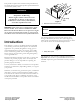
This product complies with all relevant European directives, for details please see the separate product specific Declaration of Conformity (DOC) sheet. WARNING CALIFORNIA Proposition 65 Warning Diesel engine exhaust and some of its constituents are known to the State of California to cause cancer, birth defects, and other reproductive harm. Figure 1 1. Model and serial number location Important: This engine is not equipped with a spark arrester muffler.
Contents Changing the Engine Oil and Filter ...........................36 Adjusting the Throttle Control .................................36 Adjusting the Idle Speed..........................................37 Fuel System Maintenance ...........................................37 Fuel Filter/Water Separator .....................................37 Fuel Lines and Connections .....................................38 Electrical System Maintenance ....................................38 Servicing the Battery......
Preparation Safety • While mowing, always wear substantial footwear, long This machine meets or exceeds CEN standard EN 836:1997, ISO standard 5395:1990, and ANSI B71.4-2004 specifications in effect at the time of production when 40 lb. of ballast is added to the rear wheel. • Improper use or maintenance by the operator or owner can result in injury.
Maintenance and Storage • Stop the blades from rotating before crossing surfaces other than grass. • Keep all nuts, bolts and screws tight to be sure the • When using any attachments, never direct discharge of equipment is in safe working condition. material toward bystanders nor allow anyone near the machine while in operation. • Never store the equipment with fuel in the tank inside a building where fumes may reach an open flame or spark.
• The operator must be skilled and trained in how to drive Use of this product for purposes other than its intended use could prove dangerous to user and bystanders. Operation • • Know how to stop the engine quickly. • Always wear substantial shoes. Do not operate the • • • • • • • • • • • • machine while wearing sandals, tennis shoes, or sneakers. Wearing safety shoes and long pants is advisable and required by some local ordinances and insurance regulations.
Vibration Level replacement parts and accessories. Replacement parts and accessories made by other manufacturers could be dangerous, and such use could void the product warranty. Hand-Arm Measured vibration level for right hand = 0.27 m/s2 Sound Power Level Measured vibration level for left hand = 0.29 m/s2 This unit has a guaranteed sound power level of 99 dBA, which includes an Uncertainty Value (K) of 1 dBA. Uncertainty Value (K) = 0.
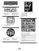
93-6681 1. Cutting/dismemberment—hazard, fan-stay away from moving parts. 93–9051 1. Read the Operator's Manual. 93-6689 1. Warning—do not carry passengers. 107–9529 1. Engine start 6. Raise the reels 11. Headlights Off 16. Throttle—slow 2. Engine preheat/on 7. High temperature override 12. Functional control lever 17. Throttle—continuous variable setting 3. Engine stop 8. Engine coolant temperature 13. Use for transport 4. Read the Operator’s Manual. 9. Water in the fuel indicator light 5.
117–2718 104–7729 1. Warning—read the instructions before servicing or performing maintenance. 93-8062 2. Cutting/dismemberment hazard; hand or foot—stop the engine and wait for moving parts to stop. 1. To lock the parking brake, press the brake pedal and the parking brake lock. 3. Parking brake lock 2. To unlock the parking brake, press the brake pedal. 93-7275 (Model 30630 & 30631) 1. Read the Operator's Manual. 2. Do not use starting aids. 117–9536 1. Warning—wear hearing protection. 2.
Battery Symbols Some or all of these symbols are on your battery 117–9537 Replaces 117–9536 for CE. 1. Explosion hazard 6. Keep bystanders a safe distance from the battery. 2. No fire, open flame, or smoking. 7. Wear eye protection; explosive gases can cause blindness and other injuries 3. Caustic liquid/chemical burn hazard 4. Wear eye protection 8. Battery acid can cause blindness or severe burns. 9. Flush eyes immediately with water and get medical help fast.
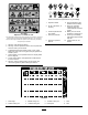
Setup Loose Parts Use the chart below to verify that all parts have been shipped. Procedure 1 2 3 4 5 6 7 8 Description Use Qty. Wheel hub Wheel nuts Wheel Wheel bolt Locknut Spacers Seat Nut (5/16 inch) 1 4 1 1 1 2 1 4 No parts required – Bolt (1/4 x 5/8 inch) Nut (1/4 inch) Anti-scalp roller Pull link assembly Roller shaft Spacer Washer Lock nut, 3/8–16 2 2 2 2 2 2 4 2 No parts required – No parts required – Offset Lift Hook Bolts, M10–1.
Note: Mounting fasteners for the Greensmaster 3250-D cutting units are included with the cutting units. 1 Installing the Rear Wheel Parts needed for this procedure: 1 Wheel hub 4 Wheel nuts 1 Wheel 1 Wheel bolt 1 Locknut 2 Spacers Figure 3 1. Rear wheel 2. Hub 3. Nut 4. Rear castor fork 5. Wheel bolt 6. Spacer (2) 6. Wipe the grease fitting clean on the wheel assembly. Pump grease into the wheel hub until grease is seen exiting at both hub bearings. Wipe up excess grease. Procedure 1.
Figure 5 1. Vent caps 3. Carefully fill each cell with electrolyte until the plates are covered with about 1/4 inch (6 mm) of fluid (Figure 6). Figure 4 1. Seat support 2. Seat slide 3 Activating and Charging the Battery Figure 6 No Parts Required 1. Electrolyte Procedure 4. Allow approximately 20 to 30 minutes for the electrolyte to soak into the plates. Fill as necessary to bring the electrolyte to within about 1/4 inch (6 mm) of the bottom of the fill well (Figure 6). Use only electrolyte (1.
Note: After the battery has been activated, add only distilled water to replace normal loss, although maintenance-free batteries should not require water under normal operating conditions. WARNING CALIFORNIA Proposition 65 Warning Battery posts, terminals, and related accessories contain lead and lead compounds, chemicals known to the State of California to cause cancer and reproductive harm. Wash hands after handling. Figure 7 1. Negative (-) 2.
WARNING 5 Battery terminals or metal tools could short against metal tractor components causing sparks. Sparks can cause the battery gasses to explode, resulting in personal injury. Mounting the Front Rollers • When removing or installing the battery, do not allow the battery terminals to touch any metal parts of the tractor. Parts needed for this procedure: 2 Anti-scalp roller • Do not allow metal tools to short between the battery terminals and metal parts of the tractor.
to 120 degrees F (49 degrees C), or using it for heavy-duty use (mowing other than greens, such as fairways or verticutting), install a Hydraulic Oil Cooler Kit, Part No. 104–7701, to the machine. 6 Adjusting the Carrier Frame Rollers 8 No Parts Required 1. Position the machine on a level surface and lower the cutting unit carrier frames to the floor. Installing the Cutting Units (For Cutting Unit Models 04610, 04611 and 04616 Only) 2. Verify that there is 1/2 in.
Figure 11 1. Prop (not provided) 2. Bedknife adjusting screw nut (2) Figure 13 1. Remove the cutting units from the cartons. Assemble and adjust them as listed in the cutting unit Operator's Manual. Use the gauge bar from the loose parts kit to adjust the height of cut. 2. Install the offset lift hook (Figure 12) to the top of the cutting unit with (2) M10–1.5 bolts. Torque the bolts to 25–30 ft–lbs. (34–40 N⋅m). The offset lift hook should be positioned with hook forward. 1. Counter weight B.
Figure 15 1. Snap ring 2. Drive coupler Figure 17 E. Apply grease to the inside diameter of the drive coupler. Install the drive coupler to the left end of the cutting unit reel tube with a snap ring. F. G. 1. Pull link extension 3. Ball joint receiver 2. Pull arm Install the motor mount to the left end of the cutting unit with the (2) allen head screws previously removed. Torque screws to 12–15 ft–lbs. (16–20 N⋅m). 8. Mount the basket onto the carrier frame. 9.
counterclockwise until the flanges are encircling the studs (Figure 18). 13. Tighten the mounting bolts (Figure 18). 9 Adjusting the Transport Height No Parts Required Procedure Figure 20 Check the transport height (Figure 19 & Figure 20) and adjust, if required. 1. Position the tractor on a level surface. 1. Transport plate 4. Link hook 2. Adjusting screw 5. 7/8 inch (22 mm) 3. Transport plate mounting screw 2.
holders in the machine frame. Damage to the motors or hoses could result. 12 6. Ensure each carrier frame is at the same height from the ground. If they are, proceed to step 8. Reading the Manuals and Viewing the Training Materials 7. If the carrier frames are not at the same height, loosen the jam nut on the carrier frame adjusting screw (Figure 19, Figure 20 and Figure 21). Rotate the screw outward to raise and inward to lower. Tighten the jam nut after the proper height is obtained.
Product Overview Controls brakes actuated for parking. Disengage it by pressing the brake pedal. Form the habit of locking the parking brake before you leave the machine. Lock the parking brake any time you leave the machine. Traction and Stopping Pedal Throttle Control The traction pedal (Figure 22) has three functions: to make the machine move forward, to move it backward, and to stop the machine.
Hour Meter Backlap Lever The hour meter (Figure 24) indicates the total hours the machine has operated. It starts to function whenever the key switch is rotated to On. Use the backlap lever (Figure 25) in conjunction with the raise/lower mow control lever and the reel speed control for backlapping the reels. Ignition Switch Insert the key into the switch (Figure 24) and turn it clockwise as far as possible to the Start position to start the engine.
Fuel Shut-Off Valve Specifications Close the fuel shut-off valve (Figure 27), under the fuel tank, when storing or transporting the machine on a truck or trailer. Note: Specifications and design are subject to change without notice. Width of cut 59 inches (150 cm) Wheel tread 50.5 inches (128 cm) Wheel base 48.6 inches (123 cm) Overall length (w/baskets) 93.9 inches (238 cm) Overall width Overall height Net Weight w/reels (8 Blade 4 Bolt) 68 inches (173 cm) 50.
Operation add enough oil to raise the level to the Full mark on the dipstick. Add the oil slowly and check the level often during this process. Do not overfill. Note: Determine the left and right sides of the machine from the normal operating position. Important: Make sure that the dipstick is removed while filling the engine with oil. When adding engine oil or filling oil, there must be clearance between the oil fill device and the oil fill hole in the valve cover as shown in Figure 28.
• The blended fuel composition should meet ASTM D975 after the first 50 hours of operation, thereafter change the oil and the filter every 150 hours. However, change the oil more frequently when the engine is operated in extremely dusty or dirty conditions. or EN590. • Painted surfaces may be damaged by biodiesel blends. • Use B5 (biodiesel content of 5%) or lesser blends in cold weather 5. Install the filler cap and dipstick firmly in place.
CAUTION If the engine has been running, the pressurized, hot coolant can escape and cause burns. • Do not open the radiator cap when the engine is running. • Use a rag when opening the radiator cap, and open the cap slowly to allow steam to escape. Figure 30 1. Fuel tank cap 1. Park the machine on a level surface. 2. Check the coolant level (Figure 32). It should be between the lines on the reserve tank when the engine is cold. 2. Remove the fuel tank cap. 3.
Note: Toro will not assume responsibility for damage caused by improper substitutions, so use only products from reputable manufacturers who will stand behind their recommendation. the biodegradability and toxicity of this oil. When changing from standard fluid to the biodegradable type, be certain to follow the approved flushing procedure. Contact your local Toro Distributor for details.
3. If the fluid level is low, slowly fill the reservoir with the appropriate hydraulic fluid until the level reaches the bottom of the screen. Do not overfill. Vary the tire pressure for the rear wheel from a minimum of 8 psi to a maximum of 15 psi (55 to 103 kPa). Important: To prevent system contamination, clean the top of the hydraulic fluid containers before puncturing. Ensure the pour spout and funnel are clean.
• Initial start up of a new engine • The engine has ceased running due to lack of fuel. • Maintenance has been performed upon fuel system 3. Close the breather valve. components; ie. filter replaced, etc. Refer to Bleeding the Fuel System. Important: Do not use ether or other types of starting fluid. 1. Be sure the parking brake is set, the raise/lower mow control is disengaged, and the functional control is in the neutral position. 2.
engage the parking brake. Try to depress the traction pedal. The pedal should not depress, which means that the interlock system is operating correctly. Correct the problem if it is not operating properly. 2. Sit on the seat, move the traction pedal to Neutral, move the functional control lever to Neutral, and engage the parking brake. Move the functional control lever to mow or transport and try to start the engine. The engine should not crank, which means that the interlock system is operating correctly.
timing necessary to minimize the cleanup mowing operation. 3. Overlap a minimal amount with the previous cut on return passes. To assist in maintaining a straight line across the green and keep the machine an equal distance from the edge of the previous cut, establish an imaginary sight line approximately 6 to 10 ft (1.8 to 3 m) ahead of the machine to the edge of the uncut portion of the green (Figure 39). Some find it useful to include the outer edge of the steering wheel as part of the sight line; i.e.
Transport Operation Important: The machine should never be stopped on a green with the cutting unit reels operating as damage to the turf may result. Stopping on a wet green with the machine may leave marks or indentations from the wheels. Make sure the cutting units are in the full up position. Move the functional control lever to the transport position. Use the brakes to slow the machine while going down steep hills to avoid loss of control.
Maintenance Note: Determine the left and right sides of the machine from the normal operating position. Recommended Maintenance Schedule(s) Maintenance Service Interval After the first hour Maintenance Procedure • Check the torque of the wheel nuts. After the first 8 hours • Check the tension on the alternator belt. After the first 10 hours • Check the torque of the wheel nuts. After the first 50 hours • Change the engine oil and filter. • Change the hydraulic oil filter.
Daily Maintenance Checklist Duplicate this page for routine use. Maintenance Check Item For the week of: Mon. Tues. Wed. Thurs. Fri. Sat. Check the safety interlock operation. Check the instrument operation Check the brake operation. Check the fuel filter/water separator. Check the fuel level. Check the engine oil level. Clean the screen and radiator. Inspect the air filter. Check any unusual engine noises. Check the reel-to-bedknife adjustment. Check the hydraulic hoses for damage.
Lubrication Greasing the Bearings and Bushings Service Interval: Every 50 hours (more frequently when operating conditions are dusty or dirty) The machine has grease fittings that must be lubricated regularly with No. 2 General Purpose Lithium Base Grease. If the machine is operated under normal conditions, lubricate all bearings and bushings after every 50 hours of operation. Lubricate fittings immediately after every washing, regardless of the interval listed.
Engine Maintenance 4. Clean the dirt ejection port located in the removable cover. Remove the rubber outlet valve from the cover, clean the cavity and replace the outlet valve. 5. Install the cover orienting the rubber outlet valve in a downward position – between approximately 5:00 to 7:00 when viewed from the end. 6. Reinstall the cover and secure the latches (Figure 44). Servicing the Air Cleaner Service Interval: Every 50 hours • Check the air cleaner body for damage which could cause an air leak.
Fuel System Maintenance 3. Move the cable until the speed control lever contacts the idle speed screw (Figure 45). 4. Tighten the cable clamp screw and check the engine RPM setting. • High Idle: 2925 ± 50 RPM Fuel Filter/Water Separator • Low Idle: 1500 ± 50 RPM Service Interval: Every 800 hours Adjusting the Idle Speed Servicing the Filter 1. Close the fuel shut off valve (Figure 46) below the fuel tank. 1. Move the remote throttle control lever to the Slow position. 2.
Electrical System Maintenance 6. Loosen the carriage bolt on the filter mounting band and remove the filter canister. Dispose of properly. 7. Install the new filter canister and tighten the mounting band carriage bolt. Servicing the Battery 8. Install the fuel lines and clamps per the inlet and outlet markings on the top of the filter. 9. Make sure the filter drain plug is closed. Open the fuel shut off valve.
WARNING Battery terminals or metal tools could short against metal tractor components causing sparks. Sparks can cause the battery gasses to explode, resulting in personal injury. • When removing or installing the battery, do not allow the battery terminals to touch any metal parts of the tractor. • Do not allow metal tools to short between the battery terminals and metal parts of the tractor. WARNING Figure 48 Incorrect battery cable routing could damage the tractor and cables causing sparks.
Drive System Maintenance Adjusting the Transmission for Neutral If the machine creeps when the traction control pedal is in the neutral position, the neutral return mechanism must be adjusted. 1. Block up under the frame so that one of the front wheels is off of the floor. Figure 49 Note: Note: If machine is equipped with a 3 wheel drive kit, also raise and block rear wheel. 1. Traction cable 2. Bulkhead 3. Jam nuts 2.
Cooling System Maintenance Cleaning the Radiator Screen To prevent the system from overheating, the radiator screen and radiator must be kept clean. Check and clean the screen and radiator daily or, if necessary, hourly. Clean these components more frequently in dusty, dirty conditions. 1. Remove the radiator screen (Figure 52). 2. Working from the fan side of the radiator, blow out the radiator with compressed air. Figure 51 1. Jam nut 2. Nut 3. Trunnion bolt 3.
Brake Maintenance Belt Maintenance Adjusting the Brakes Adjusting the Belt A brake adjustment rod is located on each side of the machine so that the brakes can be equally adjusted. Adjust the brakes as follows: Service Interval: After the first 8 hours Make sure the belt is properly tensioned to ensure proper operation of the machine and prevent unnecessary wear. 1. While moving forward in transport speed, press the brake pedal; both wheels should lock equally. 1.
Controls System Maintenance 1. Position the machine on a level surface, lower the cutting units, stop the engine, engage the parking brake. 2. Unlock and raise the seat to expose the controls. 3. Make initial reel to bedknife adjustments appropriate for backlapping on all cutting units which are to be backlapped; refer to the Cutting Unit Operator’s Manual. Adjusting the Cutting Unit Lift/Drop DANGER The cutting unit lift/drop circuit is equipped with a flow control valve (Figure 55).
Hydraulic System Maintenance compound off of the cutting units. Adjust cutting unit reel to bedknife as needed. Move the cutting unit reel speed control to the desired mowing position. Important: If the backlap lever is not returned to the “F” position after backlapping, the cutting units will not raise or function properly.
Checking the Hydraulic Lines and Hoses Storage If you wish to store the machine for a long period of time, the following steps should be performed prior to storage: WARNING 1. Remove accumulations of dirt and old grass clippings. Sharpen the reels and bedknives, if necessary; refer to the Cutting Unit Operator's Manual. Use a rust preventive on bedknives and reel blades. Grease and oil all lubrication points; refer to Lubrication.
Schematics Electrical Schematic (Rev.
Hydraulic Schematic (Rev.
The Toro Total Coverage Guarantee A Limited Warranty Conditions and Products Covered The Toro® Company and its affiliate, Toro Warranty Company, pursuant to an agreement between them, jointly warrant your Toro Commercial product (“Product”) to be free from defects in materials or workmanship for two years or 1500 operational hours*, whichever occurs first. This warranty is applicable to all products with the exception of Aerators (refer to separate warranty statements for these products).