
Operator's Manual


3
Setup
Note: Determine the left and right sides of the machine from the normal operating position.
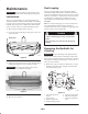
Loose Parts
Description Qty. Use
Ball stud
Internal tooth lock washer, 3/8 in.
2
2
Mounting the front roller
Flange locknut 2 Mounting the reel drive motor to the cutting unit
Registration card 1 Fill out and return to Toro.
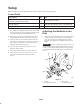
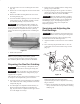
1. The cutting unit is shipped without a front roller. Install
the roller using the loose parts supplied with the cutting
unit and the instructions included with the roller.
2. Retain the two flange nuts supplied in the loose parts
for mounting the reel drive motor to the cutting unit.
3. Check for looseness in the bearings between the end
plate and reel by moving the reel laterally or axially on
each end of the cutting unit; refer to Servicing and
Adjusting the Reel Bearings, page 7.
4. Check the drive end of the reel for grease. Grease
should be visibly evident.
5. Ensure that all nuts and bolts are securely fastened.
6. Check the level of the rear roller to the reel; refer to
Leveling the Rear Roller Assembly to the Reel,
page 9.
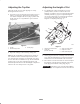
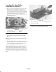
Adjusting the Bedknife to the
Reel
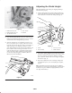
1. Loosen the bottom adjustment screw on each side of the
cutting unit (Fig. 2); then tighten the top adjustment
screw on each side of the cutting unit (Fig. 3). This
adjustment will position the bedknife closer to the reel
blades.
Important Use only an open end wrench 3 to 6 in. (7.6
to 15.2 cm) in length for adjusting the bedknife to the reel.
A longer wrench will provide too much leverage and may
cause distortion of the mounting plate for the adjustment
screws.
1
m–5080
2
3
4
Figure 2
1. Bedknife
2. Bottom adjustment screw
3. 3/8 in. wrench
4. Top adjustment screw