
Operator's Manual


7
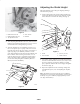
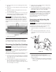
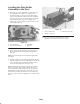
2. Loosen the Allen set screws anchoring the roller shaft
(Fig. 10).
3. Remove the rear roller height-of-cut brackets from both
side plates.
4. Remove the bedbar mounting bolts from each end of
the cutting unit (Fig. 10).
5. Loosen the bedknife adjusting screws at each end of the
cutting unit (Fig. 10). The bedknife assembly can then
be removed by rotating it away from the reel.
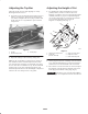
Important When installing the bedbar assembly, be
sure to position the center portion of the grass shield over
the rear edge of the bedbar (Fig. 11). Securely seat the two
bedbar pivot bolts to a maximum of 40 ft.-lb. (54 N⋅m).
Always check the bearing adjustment after assembling the
bedbar.
Figure 11
1. Bedbar under lip of shield
Note: For proper grinding of the bedknife, grind in
accordance with the procedures in the Toro Sharpening
Reel and Rotary Mowers Manual, Form No. 80-300PT.
Preparing the Reel for Grinding
Important To prevent damage to the hydraulic hoses,
remove the reel motors before removing the cutting units.
Important Some reel grinders may require that the rear
roller assembly be mounted to the cutting unit for proper
support in the reel grinder.
The front roller may have to be removed so that the reel can
be sharpened. To accomplish this, proceed as follows:
1. Loosen the locknuts securing the height-of-cut adjusting
rods at both ends of the cutting unit and the roller shaft
clamp bolts (Fig. 10).
2. Turn the height-of-cut adjustment knobs until they are
disconnected from the height-of-cut adjusting rods
(Fig. 10). The knobs are captivated on the upper washer
face of the height-of-cut clamp.
3. Remove the roller assembly from the cutting unit by
pulling evenly on both sides.
4. For proper grinding of the reel, grind in accordance
with the procedures in the Toro Sharpening Reel and
Rotary Mowers Manual, Form No. 80-300PT.
Important After the grinding operation is complete,
assemble the cutting unit, check the bearing adjustment,
and adjust the top shield and bar; refer to Adjusting the
Shield Height, page 4, and Adjusting the Top Bar,
page 5. Backlap the cutting unit to complete the
sharpening operation.
Servicing and Adjusting the
Reel Bearings
Important To prevent damage to the hydraulic hoses,
remove the reel motors before removing the cutting units.
Periodically check the drag on the reel bearings. They
should be checked in the following manner:
1. Adjust the bedknife so that it is not in contact with the
reel.
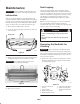
2. The reel bearing drag should be from 7 to 11 in.-lb.
(1 N⋅m) This can be measured with a torque wrench
(Fig. 12).
m–5094
Figure 12
If the bearing drag does not meet the above
specification, the procedure to adjust the reel bearing
drag is as follows:
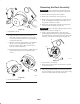
A. Remove the mounting nuts from the counterbalance
end cap and remove the end cap from the mounting
studs (Fig. 13).