
Operator's Manual


8
m–50931
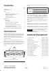
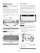
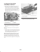
Figure 13
1. Counterbalance end cap
B. Remove the bolt mounted on the end of the reel
shaft. This will make it possible for a large socket
wrench to be mounted on the reel bearing adjusting
nut inside the side plate.
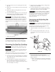
C. With the wrench mounted, hold the reel and tighten
the large reel bearing adjustment nut (Fig. 13).
Tighten it until the drag on the reel meets the 7 to
11 in.-lb. (1 N⋅m) specification.
D. Install the bolt into the end of the reel shaft (Fig. 13)
and check the torque with an inch/pound torque
wrench.
m–5095
1
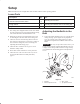
Figure 14
1. Reel bearing adjustment nut
Removing the Reel Assembly
Important To prevent damage to the hydraulic hoses,
remove the reel motors before removing the cutting units.
1. Remove the front and rear roller assembly.
2. Remove the counterbalance end cap (Fig. 13).
3. Remove the large bearing adjustment nut from one end
of the reel shaft (Fig. 14) and the special spline nut at
the opposite end of the reel shaft.
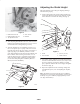
4. Remove the mounting bolts from the bearing housing
on both ends of the cutting unit (Fig. 15).
Important Remove the grease fittings from the bearing
housing at each end of the cutting unit.
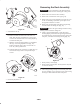
5. Using a plastic headed hammer, rotate the bearing
housing slightly, install the bearing housing bolts from
the outside housing, turn the bolts alternately against the
side plate, and remove the bearing housing (Fig. 15).
1
2
m–5096
Figure 15
1. Bearing housing—rotate slightly
2. Bearing housing mounting bolts—thread against the side plate
to remove the housing
6. The bearing housing will slip out of the side plates and
the reel assembly can be removed as soon as the bearing
housings are disassembled from the side plates.