
Installation Instructions

FORM NO. 3314-712
The TORO Company - 1991 TPS
INSTALLATION
INSTRUCTIONS
VARIABLE TRACTION SPEED KIT
MODEL NO. 04422
NOTE: These installation instructions cover the mounting procedures for both the Greensmaster 3100 and
Greensmaster 3000 D. Different parts are required for each application. Refer to loose parts chart and installa
tion instructions to identify different parts when installing kit. Retain unused parts for future applications.
LOOSE PARTS CHART
Note: Use this chart as a checklist to assure all parts necessary for assembly have been received. Without these parts,
installation cannot be completed.
DESCRIPTION QTY. QTY. USE
GR3000D GR3100
Flow Control Valve 1 1 Install on left valve cover.
Capscrew 1/4-20 x 2-1/4" 2 2 Secure flow control valve to cover.
Locknut 1/4-20 2 2
45 Adjustable Elbow 2 0 Install in "IN" valve port and in pump.
Straight Fitting 0 1 Install in "CF" valve port.
90 Adjustable Elbow 2 2 Install in "EX" & "CF" valve ports on GR 3000D.
Install in "EX" & IN" valve ports on GR 3100.
Swivel Run Tee 1 1 Install in return manifold.
Hydraulic Hose-Return (#68-5790) 1 1 Connect to EX" valve port & tee fitting
in return manifold.
Hydraulic Hose-Flow Control (#68-5820) 1 1 Connect to CF" valve port & main valve.
Hydraulic Hose-Pressure (#68-5800) 1 0 Connect to IN" valve port & pump outlet port.
Hydraulic Hose-Pressure (#83-2270) 0 1 Connect to IN" valve port & pump outlet port
Cable Tie 3 3 Tie hoses together.
Traction Control Decal (#74-3490) 1 0 Install on left valve cover.
Traction Control Decal (#83-2270) 0 1 Install on left valve cover.
Installation Instructions 1 1
Parts Catalog 1 1
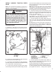
REMOVE VALVE COVERS
Greensmaster 3000 D
1. To prevent electrical damage, disconnect battery
ground cable from battery.
2. Remove screws securing left valve cover to frame.
3. Remove (4) bolts, washers and strap spacer secur
ing hydraulic filter to valve cover and lift off cover. Dis
card the strap spacer.
4. To expose mounting holes in left cover, remove
TORO decal.
5. Remove screws securing right valve cover to frame.
6. Remove knob from shift selector and lift right valve
cover off. Tip seat up and secure it to steering column to
prevent it from falling.
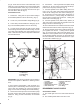
Greensmaster 3100
1. To prevent electrical damage, disconnect battery
ground cable from battery.
2. Remove screws securing left valve cover to frame.
3. To expose mounting holes in left cover, remove (2)
screws and nuts securing TORO logo plate and remove
plate.
4. Remove screws securing right valve cover to frame.
Lift right valve cover off.
5. Tip seat up and secure it to steering column to pre
vent it from falling.