
Installation Instructions

4
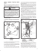
3. Using (2) capscrews and locknuts, attach variable
traction speed valve to left valve cover and secure valve
cover to frame (Fig. 5).
Figure 5
1. Left fender (Gr 3000 D)
2. Selection plate
3. Variable traction valve handle
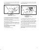
4. Assemble selection plate decal to valve and cover
and install handle on valve (Fig. 5). Lower the seat.
5. Re-install center cutting unit and check hydraulic
oil level. Add oil, as necessary.
6. Re-connect battery cable, start engine, check for
leaks and repair as necessary.
7. Check operation of variable traction speed kit. De
termine desired ground speed. After desired ground
speed has been determined, lock handle by rotating
knob clockwise.
REASSEMBLE VALVE COVERS
Greensmaster 3100
1. Re-install right valve cover.
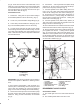
2. Using (2) capscrews and locknuts, attach variable
traction speed valve to left valve cover and secure valve
cover to frame (Fig. 6).
Figure 6
1. Left fender (Gr 3100)
2. Selection plate
3. Variable traction valve handle
mounting hole
3. Assemble selection plate decal to valve and cover
and install handle on valve (Fig. 6). Lower the seat.
4. Re-install center cutting unit and refill hydraulic
reservoir and check operation of alarm system. Refer to
Traction Unit Operator's Manual for Hydraulic oil specifi
cations, filling procedure and alarm system checks.
5. Re-connect battery cable, start engine, check for
leaks and repair as necessary.
6. Check operation of variable traction speed kit. De
termine desired ground speed. After desired ground
speed has been determined, lock handle by rotating
knob clockwise.