
Installation Instructions


3
1.06
1.50
.281”
(3)
6.44
5.59
13.75
.44
1
2
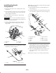
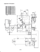
Figure 6
1. Bulkhead bracket holes 1. R–clamp hole
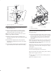
9. Mount bulkhead bracket to frame with (2) hex-head
thread-forming screws.
10. Loosely install the pump hose assembly to the 45°
fitting on pump and to the lower hole in bulkhead
bracket with a washer and a nut (Fig. 5 & 7).
Note: The 45° fitting on pump may have to be rotated
slightly to align with hose assembly.
11. Insert R–clamp onto pump hose assembly. Secure
R–clamp to frame tube with a hex-head thread-forming
screw (Fig. 7)
12. Loosely install a hydraulic hose to the pump hose
assembly (lower bulkhead) and to upper wheel motor
fitting (Fig. 5).
13. Loosely install a hydraulic hose to hydraulic hard line
(upper bulkhead) and to bottom wheel motor fitting.
1
3
2
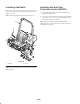
Figure 7
1. Pump
2. Pump hose assembly
3. 45 fitting
Note: The hoses must not contact tire or rim.
14. Tighten fittings.
15. Turn steering fork fully side to side to check for proper
hose flex and position. With steering wheel in full right
turn, it may be necessary to rotate rear hydrostat hose
fitting slightly downward to gain clearance with rear
wheel motor.
Note: The hoses should not rub on tire, rim, tanks, steering
fork, or steering hoses. It may be necessary to rotate fuel
shut off fitting (under fuel tank) slightly to avoid fuel filter
touching three wheel drive hoses.
Note: The hydraulic lines must not be twisted, kinked, have
sharp bends, or touch sharp edges, moving parts, or engine
exhaust parts.
16. Tighten all fittings and clamps.
17. Fill and check hydraulic oil reservoir level.
18. Connect positive then negative battery cables to battery.
Note: Connect negative cable last.
19. Start engine and cycle the traction and lift cylinders to
purge the air.
20. Re–check hydraulic oil level.