FORM NO. 3312-735 MODEL NO. 04445 — 60001 & UP . MODEL NO. 04450 — 60001 & UP OPERATOR'S Rio MODEL NO. 044568 — 60001 & UP MANUAL () L GREENS MASTER" 300 CUTTING UNIT J Since this operator’s manual covers only a minimal amount of information necessary 10 maintain and operate your machine, we suggest that you keep this material with your Traction Unit Operator's Manual so that both may be referred to for instructions concerning safe operation and proper maintenance procedures.
TABLE OF CONTENTS Page Page LOOSE PARTS . .2 LUBRICATION . L7 SPECIFICATIONS . | 2 MAINTENANCE AND ADJUSTMENTS 7-10 KNOW YOUR CUTTING UNIT . 3 Reel Lapping 7 SETTING UP INSTRUCTIONS .
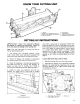
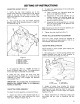
KNOW YOUR CUTTING UNIT BwN . Lift bail 5 . Height of cut adjustment knot (2] 8, . Height of cat adjustment lockout (2] 7. . Pull rod studs (2} 8 Grass shield Reel assembly Height of cut brackets (2] . Bed knife adjusting knob SETTING UP INSTRUCTIONS IMPORTANT: Read the Operator's Manual thoroughly for setting up instructions. Failure to do so may result in damage to the cutting unit. Note: Left and right sides of cutting unit refer wo normal operating position. 1.
SETTING UP INSTRUCTIONS 3. Slide bolts thru each bracket until brackets can be realigned with appropriate mounting hole. See table {Fig. 3} for proper position on brackets. Note: The various rear roller bracket positioning holes {A thru E) are designed to optimize bed knife location for different heights of cut. To determine the correct hole setting, find the desired height of cut in the chart below and note the recommended hale position letter. The typical height of cut values can be used as a guide.
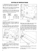
SETTING UP INSTRUCTIONS ADJUSTING HEIGHT OF CUT 1. Verify the rear roller brackets are in the correct hole positions corresponding with desired height of cut and that rear rosier is level. Also, check that bed knife to reel contact is correct. {See Table — Fig. 3). 2. Turn cutting unit over and loosen lockouts securing front roofer adjusting screws to Height of Cut brackets {Fig. 7). Figure 7 Height of cut knob lack nut Gauge bar (1-87831 Gauge bar screw head Height of cut knob .
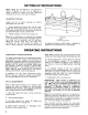
SETTING UP INSTRUCTIONS Note: Shield can be lowered in dry grass conditions {clippings fly over top of baskets) or raised to allow for heavy wet grass conditions (clippings build up on rear edge of baskets}. ADJUSTING TOP BAR Adjust top bar to assure clippings are cleanly discharged from reel area: 1. Loosen screws securing top bar (Fig. 9}. Inset 0.060 inch feeler gauge between top of reel and bar and tighten screws {Fig. 8). Assure bar and reel are equal distance apart across complete reel, 2.
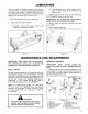
LUBRICATION There are eight {8) grease fittings on each cutting unit {Fig. 10 & 11}, which should be greased at least once every two weeks. Lubricate using a2 No. 2 multi-purpose lithium base grease. A hand operated grease gun is recommended for best results. 1. Wipe each grease fitting with a clean rag. 2. Grease reel bearings as follows: A. Hydraulic motor end; apply grease until pressure is felt against handle. 8.
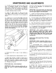
MAINTENANCE AND ADJUSTMENTS 2. Rotate adjustment knob and pivot assembly clockwise {left hand thread) until it is threaded from bed bar pivot (Fig. 12). 3. Loosen ajar nuts retaining right and left bed bar pivot blats. Remove pivot bolts {(Fig. 12}, IMPORTANT: Note position of plastic washer and steel washer on right end of bed bar, and plastic washer on left end of bed bar for re installation. 4, Slide bed bar down and out from under cutting unit, Do not misplace washers.
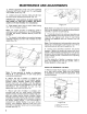
MAINTENANCE AND ADJUSTMENTS 2. On either end of front side of reel, insert a Jon strip of newspaper between reel and bed knife. While slowly rotating reel forward, turn bed knife adjusting knob (Fig, 15} clockwise, one click at a time, until paper is pinched lightly, which resits in a slight drag when paper is puled. 3. Check for light contact at other end of reel using paper. If light contact is not evident at both ends, bed knife is not parallel 1o reel, proceed to step 4. 4.
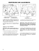
MAINTENANCE AND ADJUSTMENTS Figure 17 1. Height of cut knockout 4. End cap mounting nuts 2. Roller shaft clamp bot 5. Counterbalance end cap 3. Height of cut knob 6. Riel bewaring adjustment nut 3. With the wrench mounted, hold the reel and tighten the large reel bearing adjustment nut {Fig. 17). Tighten until the drag on the reel meets 10 to 20 inch-pound specification. 4.
i AL he Tue Promise A ONE YEAR LIMITED WARRANTY The costs of pairs and labor are included, but the customer pays the transportation cost o walk rotary powers with crating unit widths of less than 257, Commercial Products 1 Year The costs of parts and labor are included, but the customer pays the transportation costs on walk rotary mowers, trimmers and blowers. 1 you feel your TOR product is defective and wish to rely on The Toto Promise, the following procedure is recommended: 1.