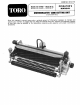
FORM NO. 3314175 MODEL NO. 04460 — 00701 & UP OPERATOR'S MODEL NO.
TABLE OF CONTENTS Page LOOSE PARTS . . SPECIFICATIONS KNOW YOUR CUTTING UNIT SETTING UP INSTRUCTIONS Leveling Rear Roller to Reel . Adjusting Height-of-Cut .. Adjusting Shield Height Adjusting Top Bar Setting Groomer Height/Depth . OPERATING INSTRUCTIONS .. LUBRICATION . . MAINTENANCE AND ADJUSTMENTS 10-1 wwe! ! R BROWNSTONE Cleaning Groomer Reel Blade Inspection . .10 Grooming Reel Replacement . 10 Reel Lapping 11 Removing Bed knife Parable! Bed knife to Reel . 12 Preparing Real for Grinding ..
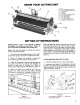
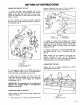
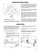
Q KNOW YOUR CUTTING UNIT ¥ of cut adjustment knob (2} #41 of cut adjustment Jock nut (2] er micro adjustment knob {21 ite adjustment knob wer reel assembly er chits soberer engage/disergage knob er quick up/ down Ever (2] SETTING UP INSTRUCTIONS IMPORTANT: Read the Operator’s Manual thoroughly for setting up instructions. Failure to do so may result in damage to the cutting unit. Note: Left and right sides of cutting unit refer to normal operating position, 1.
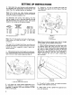
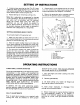
SETTING UP INSTRUCTIONS 3. Slide bolts thru each bracket until brackets can be realigned with appropriate mounting hole. See table {Fig. 3) for proper position on brackets, Note: The various rear roller bracket positioning holes (B thru E} are designed to optimize bed knife location for different heights of cut. To determine the correct hole setting, find the desired height of cut in the chart below and note the recommended hole position letter. The typical height of cut values can be used as a guide.
SETTING UP INSTRUCTIONS ADJUSTING HEIGHT OF CUT 1. Verify the rear roller brackets are in the correct hole positions corresponding with desired height of cut and that rear roller is level. Also, check that bed knife to reel contact is correct. {See Table — Fig. 3}. 2. Turn cutting unit over and loosen lockouts securing front roller adjusting screws to Height of Cut brackets (Fig. 7). Figure 7 7. Longueurs (2) 2 Gouge bar 3. Screw bead over knitted & Adjustment knob (2} 3.
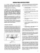
SETTING UP INSTRUCTIONS 1. Loosen screws securing top bar {Fig. 9). Insert 0.060 inch feeler gauge between top of reel and bar and tighten screws (Fig. 9). Assure bar and reel are equal distance apart across complete reel. 2. Repeat settings on remaining cutting units. Note: Bar is adjustable to compensate for changes in turf conditions. Bar should be adjusted closer to reel when turf is extremely wet, By contrast, adjust bar further away from reel when turf conditions are dry.
OPERATING INSTRUCTIONS 6. If excessive contact is felt, turn bed knife adjusting knob counterclockwise, one click at a time until no contact is evident. Then turn bed knife adjusting knob one click at a time clockwise, untie light contact is fat and heard. 7. Reassemble motor to cutting unit. {IMPORTANT: Light contact is preferred at all times.
OPERATING INSTRUCTIONS TEST GROOMER PERFORMANCE IMPORTANT: Improper or over aggressive use of the grooming reel too deep or too frequent grooming) may cause unnecessary stress on the turf leading to severe greens damage. Use the groomer cautiously. A e Before making any adjustments to cutting units disengage the reels, set the parking brake, turn the engine off and remove the key.
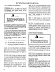
OPERATING INSTRUCTIONS Figure 12 1. Latch snubbed 2. Crutch knob 3 Quick up fever (21 GRASS BASKET AND ROLLERS When using the grooming reel with grass baskets, check the gap between the basket and the grooming reel. The reel to basket gap should be 1/4 inch. When the reel is in the fully raised {transport) position it may contact the basket and damage it if the clutch is engaged. To change the basket gap, adjust the pull arms {see procedure in the GREENS MASTER Traction Unit Operator’s Manual.
MAINTENANCE AND ADJUSTMENTS CLEANING Hose the cutting unit and groomer assembly down thoroughly after use. To prevent seal damage and contamination, do not direct the stream at the groomer bearing seals. To prevent rust, do not leave the cutting units stand in water GROOMER REEL BLADE INSPECTION Inspect grooming reel blades frequently for damage and wear. Straighten bent blades with a pliers. Either replace worn blades or reverse the grooming ree! shaft to put the sharpest bide edge forward (Fig. 15).
MAINTENANCE AND ADJUSTMENTS Morgue the drive pulley and lockout {left hand thread) to 28-35 ft-In {Fig. 17). Check drive belt tension. There should be 1/4 inch deflection when a force of 5-10 Ib is applied midway between the drive and driven pulleys {Fig. 17}. To adjust belt tension, loosen the backside idler pivot screw and pivot the idler to achieve proper tension, Torque the pivot screw to 7-10 phi-lo. 5. Using & hand pump grease gun, lubricate the grooming reel shaft bearings.
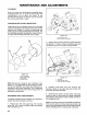
MAINTENANCE AND ADJUSTMENTS IMPORTANT: Always use Clubbed {Toto Part No. 505-35) on bed bar pivot and pivot obits. 7. Mount left side of bed bar to side plate with eccentric pivot bolt, jam nut and plastic washer. Position washer between bed bar and side plate. Thread pivot bolt into bed bar until the distance from top of pivot bolt and side plate is with identification dot positioned to rear. Do not tighten jam nut st this time (Fig. 20). Figure 20 8.
MAINTENANCE AND ADJUSTMENTS Figure 22 PREPARING REEL FOR GRINDING {IMPORTANT: Before removing cutting unit, remove reel motors to prevent damaging hydraulic hoses. The front roller may have to be removed so that the reel can be sharpened. To accomplish this, proceed as follows: IMPORTANT: Some reel grinders may require that the rear roller assembly be mounted to the cutting unit for proper support in the reel grinder. 1.
MAINTENANCE AND ADJUSTMENTS 3 Remove the grooming reel adjustment knob assembly from the belt drive housing {Fig. 24). A CAUTION The adjustment knob assembly is spring goaded. Figure 24 4. Groomer driven pulley 5. Crutch assembly 6. Groomer reef housing 1. Drive bkt 2 Drive belt inter pulley 3. Grooming reel adjustment rob assembly 4. Remove the groomer driven belt pulley and clutch adapter assembly from the reel shaft and remove the left side groomer reel housing (Fig. 24}, 5.
ONE YEAR LIMITED WARRANTY The Torn Promise The costs of parts and labor ave included. but the customer pays the transportation cysts on walk rotary mowers with cutting unit widths of less than 25°. Commercial Products 1 Year The costs of pairs and labor are included, but the customer pays the transportation costs on walk rotary mowers, trimmers and blowers. if you feel your TOR product is defective and wish to rely on The Toto Promise, the following procedure fs recommended: 1.