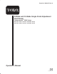
Form No. 3326-617 Rev A 8-Blade and 11-Blade Single Point Adjustment Reel Mower Greensmaster 3000 Series Model No. 04450—Serial No. 220000001 and Up Model No. 04468—Serial No.
Contents Introduction . . . . . . . . . . . . . . . . . . . . . . . . . . . . . . . . Safety . . . . . . . . . . . . . . . . . . . . . . . . . . . . . . . . . . . . . Safety and Instruction Decals . . . . . . . . . . . . . . . . Optional Equipment . . . . . . . . . . . . . . . . . . . . . . . . . . Setup . . . . . . . . . . . . . . . . . . . . . . . . . . . . . . . . . . . . . Loose Parts . . . . . . . . . . . . . . . . . . . . . . . . . . . . . . Leveling the Rear Roller to the Reel . . . . . . . . . .
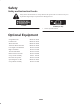
Safety Safety and Instruction Decals Safety decals and instructions are easily visible to the operator and are located near any area of potential danger. Replace any decal that is damaged or lost. 77-0490 93-6691 (for CE) 1. Read the Operator’s Manual. Optional Equipment Swaged Roller Kit Model No. 04414 Full Roller Kit Model No. 04412 Wiehle Roller Kit Model No. 04424 Aluminum Wiehle Roller Kit Model No. 04426 Low Height-of-Cut Bedknife Part No. 93-4264 High Cut Bedknife Part No.
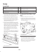
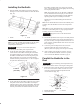
Setup Loose Parts Description Qty. Use Ball stud 2 Internal tooth lock washer, 3/8 in. 2 Flange locknut 2 Mounting the reel drive motor to the cutting unit Registration card 1 Fill out and return to Toro. Mounting the front roller 1. The cutting unit is shipped without a front roller. Install the roller using the loose parts supplied with the cutting unit and the instructions included with the roller. Leveling the Rear Roller to the Reel 2.
Note: Be sure that the plate covers the full length of the reel blades, and the three blades contact the plate. To determine the correct hole setting, find the desired height of cut in the chart below and note the recommended hole position letter. The typical height-of-cut values can be used as a guide. Table 1 Typical Height of Cut Recommended Rear Roller Bracket Hole Positions Height-of-Cut Ranges 1/8 in.* (3.18 mm) B 3/32–1/4 in. (2.38–6.36 mm) 1/4 in. (6.36 mm) C 3/16–3/8 in. (4.76–9.
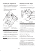
Adjusting the Height of Cut Adjusting the Shield Height 1. Verify that the rear roller brackets are in the correct hole positions corresponding with the desired height of cut and that the rear roller is level. Also, check that the bedknife to reel contact is correct (see Table 1, page 5). Adjust the shield to ensure grass clipping discharge properly into the basket. 1.
reel to ensure optimum performance and should be adjusted whenever the shield height is adjusted or whenever the reel is sharpened on a reel grinder. Note: As the reel blades continue to run against the bedknife, a slight burr will appear on the front cutting edge surface along the full length of the bedknife. Improved cutting can be obtained if a file is occasionally run across the front edge of the bedbar to remove the burr.
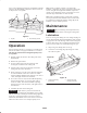
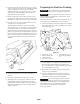
Removing the Bedknife 3. Apply grease to the front and rear roller bearings (Fig. 10 and 11) until it begins to show around the seal lips. Important To prevent damage to the hydraulic hoses, remove the reel motors before removing the cutting units. Important Do not apply too much pressure or the grease seals will be permanently damaged. 1. Remove the spring arm retaining capscrew and washer from the pivot assembly.
Installing the Bedknife the bedbar assembly firmly seats against the left side plate, clamping the plastic washer tightly and removing all end play from the bedbar. 1. Slide the bedbar into position between the side plates, making sure each end of the bedbar is under the shield (Fig. 13). Note: The shoulder bolt may be adjusted an additional 1/2 turn maximum after the end play is removed. The bedbar must pivot without binding, with the bedknife adjusting knob and pivot assembly not installed.
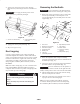
Preparing the Reel for Grinding 2. On either end of the front side of the reel, insert a long strip of newspaper between the reel and bedknife. While slowly rotating the reel forward, turn the bedknife adjusting knob (Fig. 15) clockwise, one click at a time, until the paper is pinched lightly, which results in a slight drag when paper is pulled. Important To prevent damage to the hydraulic hoses, remove the reel motors before removing the cutting unit.
Servicing and Adjusting the Reel Bearings Removing the Reel Assembly Important To prevent damage to the hydraulic hoses, remove the reel motors before removing the cutting unit. Important To prevent damage to the hydraulic hoses, remove the reel motors before removing the cutting unit. 1. Remove the counterbalance end cap (Fig. 17). Periodically check the drag on the reel bearings. They can be checked and adjusted in the following manner: 2.
The Toro General Commercial Products Warranty A Two-Year Limited Warranty Conditions and Products Covered The Toro Company and its affiliate, Toro Warranty Company, pursuant to an agreement between them, jointly warrant your 1996 or newer Toro Commercial Product (“Product”) purchased after January 1, 1997, to be free from defects in materials or workmanship for two years or 1500 operational hours*, whichever occurs first.