Form No. 3326-877 8 and 11 Blade 4-Bolt Reel Mowers Greensmaster 3250-D Model No. 04470—Serial No. 220000001 and Up Model No. 04471—Serial No.
Write the product model and serial numbers in the space below: Contents Introduction . . . . . . . . . . . . . . . . . . . . . . . . . . . . . . . . Optional Equipment . . . . . . . . . . . . . . . . . . . . . . . . . . Adjustments . . . . . . . . . . . . . . . . . . . . . . . . . . . . . . . . Adjusting the Bedknife to the Reel . . . . . . . . . . . . Choosing Cutting Unit Attitude . . . . . . . . . . . . . . Leveling the Front Roller to the Reel . . . . . . . . . . Adjusting the Top Shield Height . . . .
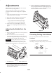
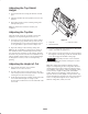
4. After the adjustment is accomplished, check to see if the reel can pinch paper when inserted from the front and cut paper when inserted at a right angle (Fig. 3). It should be possible to cut paper with minimum contact between the bedknife and the reel blades. Adjustments Note: Determine the left and right sides of the machine from the normal operating position. After the cutting unit is unboxed, use the following procedures to ensure that the cutting units are adjusted properly. 1.
Position 2 Note: A more aggressive setting may be required to compensate for reel wear. (As the reel wears, the cutting unit becomes less aggressive). Standard position; use for most conditions (factory setting). HOC Range: 0.094 (3/32)–0.72 (23/32) in. (2.4–18.3 mm) Leveling the Front Roller to the Reel Note: The top frame hole and top bracket hole will yield Position 2 (standard position). ÏÏÏÏÏÏ ÏÏÏ ÏÏÏ ÏÏÏÏÏÏ Frame Bracket 1. Position the cutting unit on a flat, level surface. 2.
Adjusting the Top Shield Height 1. Loosen bolts and nuts securing the shield to each side plate. 2. Adjust the shield to the desired position and secure the fasteners. 3. Repeat this procedure on the remaining cutting units and adjust the top bar. 3 Note: The shield can be raised for extremely wet conditions. Adjusting the Top Bar 1 Adjust the top bar, under the rear shield, to ensure that clippings are cleanly discharged from the reel area. 2 1. Loosen the screws securing the top bar. Insert a 0.
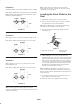
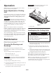
Operation Important Do not apply too much pressure or the grease seals will be permanently damaged. Note: Determine the left and right sides of the machine from the normal operating position. 4. Wipe excess grease away. Daily Adjustments of Cutting Unit 1 Prior to mowing each day, or as required, each cutting unit must be checked to verify proper bedknife-to-reel contact. This must be performed even though quality of cut is acceptable. Important Light contact is preferred at all times.
The Toro General Commercial Products Warranty A Two-Year Limited Warranty Conditions and Products Covered The Toro Company and its affiliate, Toro Warranty Company, pursuant to an agreement between them, jointly warrant your 1996 or newer Toro Commercial Product (“Product”) purchased after January 1, 1997, to be free from defects in materials or workmanship for two years or 1500 operational hours*, whichever occurs first.