Form No. 3326-890 8 and 11 Blade SPA Reel Mowers Greensmaster 3250-D Model No. 04472—Serial No. 220000001 and Up Model No. 04473—Serial No.
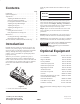
Write the product model and serial numbers in the space below: Contents Introduction . . . . . . . . . . . . . . . . . . . . . . . . . . . . . . . . Optional Equipment . . . . . . . . . . . . . . . . . . . . . . . . . . Adjustments . . . . . . . . . . . . . . . . . . . . . . . . . . . . . . . . Adjusting the Bedknife to the Reel . . . . . . . . . . . . Choosing Cutting Unit Attitude . . . . . . . . . . . . . . Leveling the Front Roller to the Reel . . . . . . . . . . Adjusting the Top Shield Height . . . .
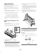
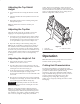
Adjustments 4. Loosen locknuts retaining the left-hand bedbar pivot housing (Fig. 2). Note: Determine the left and right sides of the machine from the normal operating position. 5. Rotate flange nuts (Fig. 2, inset), on top and bottom of frame tab, clockwise or counterclockwise to raise or lower end of bedbar, as required. Do not loosen bottom flange nut. Tighten flangenuts against frame tab when desired adjustment is attained.
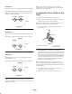
Position 2 Note: A more aggressive setting may be required to compensate for reel wear. (As the reel wears, the cutting unit becomes less aggressive). Standard position; use for most conditions (factory setting). HOC Range: 0.094 (3/32)–0.72 (23/32) in. (2.4–18.3 mm) Leveling the Front Roller to the Reel Note: The top frame hole and top bracket hole will yield Position 2 (standard position). ÏÏÏÏÏÏ ÏÏÏ ÏÏÏ ÏÏÏÏÏÏ Frame Bracket 1. Position the cutting unit on a flat, level surface. 2.
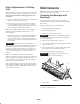
Adjusting the Top Shield Height profile. Therefore, benchsetting a cutting unit does not equal the effective (actual) height of cut you achieve. You need to determine how to adjust your cutter on the bench to achieve a comparable height of cut to a cutting unit of a different configuration, model, or brand. 1. Loosen bolts and nuts securing the shield to each side plate. 2. Adjust the shield to the desired position and secure the fasteners. 3.
Daily Adjustments of Cutting Unit Maintenance Note: Determine the left and right sides of the machine from the normal operating position. Prior to mowing each day, or as required, each cutting unit must be checked to verify proper bedknife-to-reel contact. This must be performed even though quality of cut is acceptable. Greasing the Bearings and Bushings 1. Lower the cutting units onto a hard surface, shut off the engine, and remove the ignition key.
Backlapping the Cutting Units Caution Contact with the reels or other moving parts can result in personal injury. Keep fingers, hands, and clothing away from the reels or other moving parts. 1. Position the machine on a clean, level surface, lower the cutting units, stop the engine, engage the parking brake, and remove the ignition key. 2. Remove the reel motors from the cutting units and disconnect and remove the cutting units from the lift arms. 3.
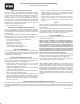
The Toro General Commercial Products Warranty A Two-Year Limited Warranty Conditions and Products Covered The Toro Company and its affiliate, Toro Warranty Company, pursuant to an agreement between them, jointly warrant your 1996 or newer Toro Commercial Product (“Product”) purchased after January 1, 1997, to be free from defects in materials or workmanship for two years or 1500 operational hours*, whichever occurs first.