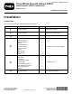
Form No. 3447-271 Rev A Three-Wheel Drive Kit without ROPS Greensmaster® 3250-D Traction Unit Model No. 04477 Installation Instructions Installation Loose Parts Use the chart below to verify that all parts have been shipped. Procedure 1 2 3 4 5 6 © 2021—The Toro® Company 8111 Lyndale Avenue South Bloomington, MN 55420 Description Use Qty. No parts required – Prepare the machine. No parts required – Remove the existing wheel. No parts required – Modify the caster fork.
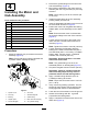
1 3 Preparing the Machine Modifying the Caster Fork No Parts Required Traction Units with Serial Number 269999999 and Below Procedure 1. Park the machine on a level surface. 2. Engage the parking brake. 3. Shut off the engine and remove the key. 4. Disconnect first the negative cable, then the positive cable from the battery. No Parts Required Procedure If the traction unit has a serial number prior to 269999999, you must modify the caster wheel fork.
4 2. Remove the grease fitting from the new motor and hub assembly (Figure 2). 3. Mount the tire assembly to the motor and hub assembly with the 4 lug nuts that you previously removed. Installing the Motor and Hub Assembly Note: Torque the lug nuts to 70 to 90 ft-lb (95 to 122 N∙m). Parts needed for this procedure: 4. Install the grease fitting to the hub assembly, pointing it away from the hub. 5. Insert the flangettes and bearing onto the end of the motor shaft as shown in Figure 2. 6.
3. 5 Refer to the dimensions shown in Figure 4 to locate, mark, and drill 4 holes (9/32 inch or 7 mm diameter) into the right-hand frame tube. Installing the Hoses Parts needed for this procedure: 4 Self-tapping screws 4 Tube clamp 2 Coverplate 2 Hex-head screw (M8) 2 Locknut (M8) 1. 11 inches (27.9 cm) +/- 1/4 3. Right-hand frame tube inch (0.6 cm) 1 Hose assembly (95-0517) 1 Hose assembly (100-6412) 2. 1 inch (25.4 mm) +/- 1/16 inch (1.
g010122 Figure 6 1. Hydrostat hose (upper) g017017 Figure 8 1. Bottom hose ends 8. Secure the hose ends to the fittings. Note: Use a backing wrench to ensure that the hose does not twist. g010123 Figure 7 1. Upper-bulkhead tee fitting 9. Secure the hoses together at the rear of the unit with a cable tie. 10. Turn the steering fork fully side-to-side to check for proper hose flex and position. Note: Remove and discard the lower hydrostat hose.
Completing the Installation No Parts Required Procedure 1. Check the hydraulic-fluid level; refer to your traction unit Operator’s Manual. 2. Connect the positive cable to the battery. 3. Connect the negative cable to the battery. 4. Start the engine. 5. Cycle the traction and lift cylinders to purge the air from the hydraulic system. 6. Check the hydraulic-fluid level.
Notes: