Form No. 3451-220 Rev A Dethatching Unit Greensmaster® 3000 Series Traction Unit Model No. 04479—Serial No. 410400000 and Up Register at www.Toro.com.
This product complies with all relevant European directives. For details, please see the Declaration of Incorporation (DOI) at the back of this publication. Model No. Serial No. This manual identifies potential hazards and has safety messages identified by the safety-alert symbol (Figure 2), which signals a hazard that may cause serious injury or death if you do not follow the recommended precautions.
Cutting Unit Safety Safety • The cutting unit is only a complete machine when This machine has been designed in accordance with EN ISO 5395 and ANSI B71.4:2017. installed on a traction unit. Read the traction unit Operator’s Manual carefully for complete instructions on the safe use of the machine.
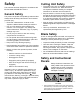
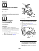
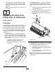
Setup 1 Installing the Front Roller No Parts Required Procedure The dethatching unit is shipped without a front roller. Install the roller using the loose parts supplied with the dethatching unit and Installation Instructions included with the roller. g016405 2 Figure 3 1. Counterweight Repositioning the Counterweights No Parts Required 3. Remove the 2 Allen-head screws that secure the motor mount to the left end of the dethatching unit. 4. Remove the motor mount (Figure 4). 5.
7. • An offset link (Part No. 110-2397) is required On the left end of the dethatching unit, apply a light coating of oil to the O-ring and install the counterweight with the screws previously removed. for the Greensmaster 3250-D traction units (it is supplied with the Greensmaster 3250-D traction unit). Note: Torque the screws to 16 to 20 N-m (12 1. Position the lift hook offset toward the front of the dethatching unit. 2.
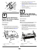
3. With the rollers contacting the level surface, loosen both flange nuts (Figure 8). 4. Rotate the height-of-cut adjusting bolts until both ends of the dethatcher are near the level surface (Figure 8). 5. Verify height by using a piece of paper to check each end of the blades. 6. Tighten both flange locknuts. g011932 5 Figure 7 2. Mounting bracket 1.
3. Loosen the flange nuts on the roller assembly. 4. Turn the height-of-cut adjusting bolt on each height-of-cut bracket so that the dethatcher blades come in contact with the level surface on both ends. Note: As the dethatcher blades wear, the diameter of the assembly will decrease and the depth setting will change. Check the depth setting periodically to ensure that the desired setting is achieved. 5. Tighten both height-of-cut flange locknuts.
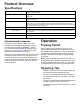
Product Overview Specifications Traction-unit compatibility Height of cut Height-of-cut range Reel bearings Rollers Grass shield Counterweight Net weight The dethatching unit mounts on the Greensmaster 3000, 3000-D, 3050, 3100, 3150, 3250-D and 3150-Q traction units. Dethatching depth is adjusted on the front roller by 2 vertical screws and held by 2 locking flange nuts Bench HOC range is 4.78 mm (0.188 inch) below ground level to 6.35 mm (0.250 inch) above ground level.
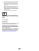
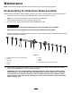
Maintenance Note: Determine the left and right sides of the machine from the normal operating position. Disassembling the Dethatcher Blade Assembly Disassemble the dethatcher blade assembly whenever you need to change a blade or replace the bearings. 1. Secure the jam nut on the end of the assembly, which contains the washer, in a vise. Note: Do not remove the washer or nut on this side of the assembly. 2. Remove the threaded spline insert, bearing, and flock seal. 3.
g379283 Figure 11 1. Index hole 6. Torque the threaded spline insert, hex bolt, and jam nut to 108 to 135 N∙m (80 to 100 ft-lb).
Servicing the Roller The Greens Roller Rebuild Kit (Part No. 140-5552) and the Greens Roller Rebuild Tool Kit (Part No. 140-5553) (Figure 12) are available for servicing the roller. The Roller Rebuild Kit includes all the bearings, bearing nuts, and seals to rebuild a roller. The Roller Rebuild Tool Kit includes all the tools and the installation instructions required to rebuild a roller with the roller rebuild kit. Refer to your parts catalog or contact your authorized Toro distributor for assistance.
Notes:
Notes:
Declaration of Incorporation The Toro Company, 8111 Lyndale Ave. South, Bloomington, MN, USA declares that the following unit(s) conform(s) to the directives listed, when installed in accordance with the accompanying instructions onto certain Toro models as indicated on the relevant Declarations of Conformity. Model No. 04479 Serial No.
The Toro Warranty Two-Year or 1,500 Hours Limited Warranty Parts Conditions and Products Covered The Toro Company warrants your Toro Commercial product (“Product”) to be free from defects in materials or workmanship for 2 years or 1,500 operational hours*, whichever occurs first. This warranty is applicable to all products with the exception of Aerators (refer to separate warranty statements for these products).