Form No. 3370-156 Rev A Dethatching Unit Greensmaster® 3000 Series Traction Unit Model No. 04479—Serial No. 312000001 and Up To register your product or download an Operator's Manual or Parts Catalog at no charge, go to www.Toro.com.
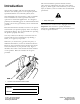
This manual identifies potential hazards and has safety messages identified by the safety alert symbol (Figure 2), which signals a hazard that may cause serious injury or death if you do not follow the recommended precautions. Introduction This product complies with all relevant European directives. For details, please see the separate product specific Declaration of Conformity (DOC) sheet.
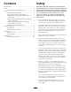
Contents Safety Introduction................................................................. 2 Safety ........................................................................... 3 Safety and Instructional Decals ............................. 4 Setup............................................................................ 5 1 Installing the Front Roller .................................. 5 2 Repositioning the Counter Weights ....................
• Remove the key from the ignition switch to prevent someone from accidentally starting the engine when servicing, adjusting, or storing the machine. parts and accessories. Never use "will-fit" replacement parts and accessories made by other manufacturers. Look for the Toro logo to assure genuineness. Using unapproved replacement parts and accessories could void the warranty of The Toro Company. • Perform only those maintenance instructions described in this manual.
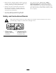
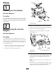
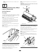
Setup 1 Installing the Front Roller No Parts Required Procedure The dethatching unit is shipped without a front roller. Install the roller using the loose parts supplied with the dethatching unit and installation instructions included with the roller. Figure 3 1. Counter weight 2 3. Remove the 2 Allen-head screws that secure the motor mount to the left end of the dethatching unit. Repositioning the Counter Weights 4. Remove the motor mount (Figure 4). 5.
Note: Torque the screws to 12 to 15 ft-lbs. (16 to 20 N-m). Note: Torque the capscrews to 25 to 30 ft-lb (34 to 40 N-m). Important: Position the lift hook offset toward the front of the dethatching unit. 3 Installing the Hoop Link, Offset Link, or Chain Link No Parts Required Procedure For dethatching units that will be mounted on a traction unit with a serial number prior to 240000001, the proper lift link must be obtained and installed.
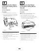
4 5 Adjusting the Reel Blades for Positive Setting (Above Ground) Adjusting the Reel Blades For Negative Setting (Below Ground) No Parts Required No Parts Required Procedure Procedure 1. Place the dethatching unit on a level surface. Note: Maximum recommended negative setting is 3/16-inch (5 mm) deep blade penetration. 2. Place a gauge bar, which has the desired height of blade above ground, under each end of the dethatching unit (Figure 8). 1. Place the dethatching unit on a level surface. 2.
6 Installing the Dethatching Unit No Parts Required Important: If you set the dethatching reel at a negative setting, take care to prevent damaging the reel blades, due to contact with concrete floors or paved surfaces. Note: The dethatching unit comes configured for left-hand drive from the factory. It may need to be configured for a right-hand drive. Refer to Repositioning the Counter Weights in this section.
Product Overview Specifications Tractors Height-of-cut These dethatching units will mount on the Greensmaster 3000, 3000-D, 3050, 3100, 3150, 3250-D and 3150-Q Traction Units. Dethatching depth is adjusted on the front roller by two vertical screws and held by two locking capscrews Height-of-cut Range Bench HOC range is .188 inch (4.78 mm) below ground level to .250 inch (6.35 mm) above ground level.
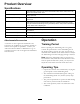
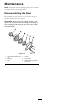
Maintenance Note: Determine the left and right sides of the machine from the normal operating position. Disassembling the Reel Disassemble the reel whenever you need to change a blade or replace the reel bearings. Important: Ensure that the 2 shaft retainers and spacer are in place before installing the bearing on the reel (Figure 10). Torque the insert nuts to 100 lb-ft (136 N-m). Figure 10 1. Left-hand threaded insert nut 2. Bearing 3. Seal 4. Spacer 5. Slot in shaft 6.
Notes: 11
The Toro Total Coverage Guarantee A Limited Warranty Conditions and Products Covered The Toro® Company and its affiliate, Toro Warranty Company, pursuant to an agreement between them, jointly warrant your Toro Commercial product (“Product”) to be free from defects in materials or workmanship for two years or 1500 operational hours*, whichever occurs first. This warranty is applicable to all products with the exception of Aerators (refer to separate warranty statements for these products).