FORM NO. 3318-306 GB Rev A MODEL NO. 04480—60001 & UP MODEL NO.
Table of Contents SPECIFICATIONS ADJUSTING THE CUTTING UNIT Adjusting The bedknife To The Reel Leveling Front Roller To The Reel Adjusting Height-of-Cut Page 2 3 4 4 5 Cutting Unit Daily Adjustments LUBRICATION Greasing Bearings And Bushings BACKLAPPING THE CUTTING UNIT 5 5 5 6 Specifications Height-of-Cut: The cutting height is adjusted on rear roller by two vertical screws and held by two locking capscrews. Bench height-of-cut range is 2.4mm to l9mm.
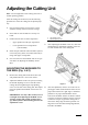
Adjusting the Cutting Unit Note: Left and right sides of the cutting unit refer to normal operating position. After the cutting unit is unboxed, use the following procedures to assure the cutting unit is adjusted properly. 1. Check each end of the reel for grease. Grease should be visibly evident in the reel bearings. 2. Insure that all nuts and bolts are securely fastened. 3. Figure 1 1. 2. Position the lift roller to match suspension.
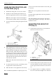
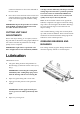
Adjusting Cutting Unit LEVELING THE FRONT ROLLER TO THE REEL (Fig. 3) screw on L.H. bracket with another eccentric bolt, part no. 93-2573. 1. Position the cutting unit on a flat, level surface. Note: There are two positions for the front roller brackets. 2. Position a 6 mm or thicker plate under the reel blades and against the front face of the bedknife. Note: Be sure the plate covers the full length of the reel blades and three blades contact the plate. 3.
Adjusting the Cutting Unit surement is from the bar face to the underside of the screw head. 4. Place the bar across the front and rear rollers and adjust the height-of-cut knob until the underside of the screw head engages the bedknife cutting edge. IMPORTANT: Repeat the procedure on each end of the bedknife and tighten locknuts that retain rear roller brackets on each end.
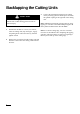
Backlapping the Cutting Units 3. CAUTION Be careful when lapping the reel because contact with the reel or other moving parts can result in personal injury. 1. Position the machine on a clean, level surface, lower the cutting units, stop the engine, engage the parking brake and remove the key from the ignition switch. 2. Remove the reel motors from the cutting units and disconnect and remove the cutting units from the lift arms.
W-X?hg W-X? W-X? W-X? W-X? W-X? W-X? W-X? W-X? W-X? W-X? W-X? W-X? W-X? W-X? W-X? W-X? W-X? W-X? W-X? W-X? W-X? W-X? W-X? W-X? W-X? W-X? W-X? W-X? W-X? W-X? W-X? W-X? W-X? W-X? W-X? W-X? W-X?hg ?W-X ?@@@@@@6X?f?W&@)Xf?W2@@@@@@@@@@@@@6Xf?W&@)XgW2@@@@@@@@@@@@6Xf?W&@)XgW2@@@@@@@@@@@@6Xf?W&@)XgW2@@@@@@@@@@@@6Xf?W&@)XgW2@@@@@@@@@@@@6Xf?W&@)XgW2@@@@@@@@@@@@6Xf?W&@)XgW2@@@@@@@@@@@@6Xf?W&@)XgW2@@@@@@@@@@@@6Xf?W&@)XgW2@@@@@@@@@@@@6Xf?W&@)XgW2@@@@@@@@@@@@6Xf?W&@)XgW2@@@@@@@@@@@@6Xf?W&@)XgW2@@@@@@@@@@@@6Xf?W&@)XgW2@@@