FORM NO. 3323-377 Rev. A MODEL NO. 04482 200000001 & UP MODEL NO.
Table of Contents Specifications Adjusting the Cutting Unit Adjusting The bedknife To The Reel Leveling Front Roller To The Reel Adjusting Shield Height Adjusting Top Bar Page 2 3 4 4 5 5 Adjusting Height-of-Cut Operating Instructions Cutting Unit Daily Adjustments Lubrication Greasing Bearings And Bushings Backlapping the Cutting Units 5 6 6 7 7 7 Specifications straps have a replaceable roller that may be moved to change transport height.
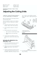
High height-of-cut kit Weilhe rear roller Full front roller Part No. 99-1496 Model No. 04488 Model No.04496 Specifications and design are subject to change without notice. Adjusting the Cutting Units IMPORTANT: Read this operator's manual thoroughly before operating the cutting unit. Failure to do so may result in damage to the cutting unit. ward, turn the bedknife adjusting knob clockwise, on click at a time, until paper is pinched lightly, which results in a slight drag while paper is pulled.
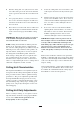
5. Rotate the flange nuts (Fig 1, inset) on the top and bottom of the frame tab, clockwise or counterclockwise to raise or lower the end of the bedbar, as required. Do not loosen the bottom flange nut. Tighten the flange nuts against the frame tab when you achieve the desired adjustment.. Position 3: More aggressive; use on firm turf or higher height of cuts. Height-of-cut range: 2.4mm–21mm Bracket Frame Down 6. Check adjustments by repeating steps 2 and 3. 7.
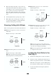
Adjusting the Top Bar Adjust the top bar, under the rear shield, to assure clippings are cleanly discharged from the reel area. 1. Loosen the screws securing the top bar. Insert a 1.5mm feeler gauge between the top of the reel and the bar and tighten the screws. Assure the bar and reel are equal distance apart across the complete reel. 2. Repeat adjusting the settings on the remaining cutting units. Figure 3 1. 2. 4.
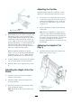
2. Turn the cutting unit over (90°) and rest it on the rear roller and top rear tabs. Loosen the locknuts on the capscrews that retain the rear roller brackets. 3. On a gauge bar (Part no. 13-8199), set the head the screw to the desired height of cut. This measurement is from the bar face to the underside of the screw head. 4. Place the bar across the front and rear rollers and adjust the height-of-cut knob until the underside of the screw head engages the bedknife cutting edge.
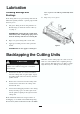
Lubrication sure or grease seals will be permanently damaged. Greasing Bearings and Bushings 4. Each cutting unit has (7) grease fittings that must be lubricated regularly with No. 2 general purpose lithium-base grease. 1. Wipe away excess grease. The grease fitting locations and quantities are: Reel bearings (2) and front and rear rollers (2 ea.) (Fig. 5). IMPORTANT: Lubricating the cutting units immediately after washing helps purge water from the bearings and increases bearing life. 2.