
Operator's Manual


1
All Rights Reserved
Printed in the USA
2001 by The Toro Company
8111 Lyndale Avenue South
Bloomington, MN 55420-1196
Rear Roller Brush Kit
Greensmaster
3200 Series
Model No. 04489
Form No. 3326-166
Installation Instructions
Note: The Rear Roller Brush Kit can be installed on cutting
unit models 04470, 04471, 04472, 04473, 04480, 04481,
04482 and 04483,
Note: Some components may have already been assembled
loosely at the factory. Some components may have to be
loosened or removed before installation. The right-hand
brush drives are shown in all figures.
Note: If the cutting unit is equipped with a Groomer, use
the instructions on page 3 for installation of this kit.
Installation for Cutting Units
without a Groomer
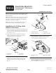
1. Remove the fasteners securing the counterweight to the
end of the cutting unit. Remove the counterweight and
plastic spacer (if so equipped). Retain the fasteners and
spacer (Fig. 1, inset).
2. Apply grease to the internal diameter of the drive
coupler. Install the drive coupler to the end of the
cutting unit with the snap ring (Fig. 1).
1
2
3
4
Figure 1
1. Counterweight
2. Snap ring
3. Drive coupler
4. Plastic spacer
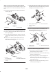
3. On the same end of the cutting unit, remove the locknut
and flat washer from the carriage bolt securing the
height-of-cut bracket to the cutting unit side plate
(Fig. 2).
1
2
3
4
Figure 2
1. Height-of-cut bracket
2. Locknut and flat washer
3. Carriage bolt
4. Cutting unit side plate
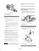
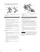
4. Thread the short (1.2” lg.) hex extension onto the
carriage bolt (Fig. 3). Tighten the hex extension
securely against the cutting unit side plate.
1
2
Figure 3
1. Short hex extension
(1.2” lg.)
2. Lower bedbar adjuster
bolt
5. Repeat steps 3 and 4 on the opposite end of the cutting
unit using the long (1.8” lg.) hex extension. Check and
adjust the height-of-cut as required.